Checking the Workstation According to the Check List Chapter 5 - Preuse Checkout
Apollo Operator’s Manual 59
Part Number: 90 38 237, 6th edition
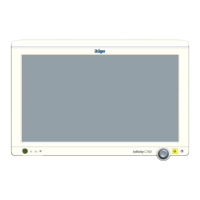
2. Check the pipeline gas supply by verifying that
the pipeline LEDs on the front panel light up
green (1 in Figure 39). The LEDs light up green
when all pipeline supplies are available and the
pressures are between 39 psi and 100 psi.
Figure 39. Location of Pipeline and Cylinder Pressure
LEDs
If the LEDs remain dark, it means that the
pipeline gas pressure is less than 39 psi or that
the hoses are not connected.
Note: Only the gas supplies selected in the
Standby Configuration screen will be
checked during the self test and normal
operation. Either pipeline or cylinder O
2
(or both) must be selected in the
Standby Configuration screen (see
page 156).
3. Check the cylinder gas supply:
a. Using the provided cylinder wrench, slowly
open the cylinder valves.
b. Verify that the cylinder pressure LEDs light
up green (2 in Figure 39). The LEDs light up
green when the cylinder pressure for O
2
and
air is over 290 psi and the pressure for N
2
O
is over 145 psi.
The cylinder pressures are shown in the
Check List screen.
c. Close the cylinder valves.
Note: A blinking cylinder pressure LED indicates
that the cylinder pressure transducer on the
back of the machine is disconnected.
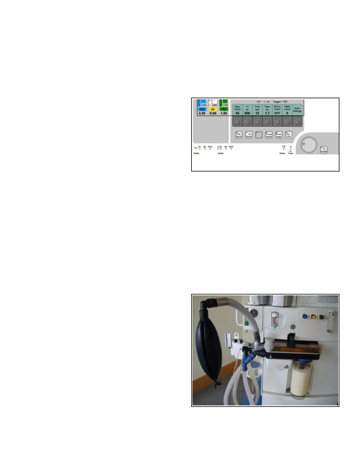
Figure 40. Component Locations
4. Test the O
2
flush (O
2
must be connected for this
test):
a. Occlude the Y-piece.
b. Press the O
2
+ button on the front of the
machine (1 in Figure 40).
c. Verify that the breathing bag inflates with an
audible flow.
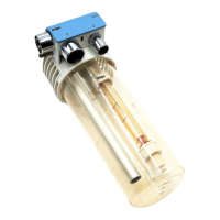
5. Test the Auxiliary O
2
flowmeter. Adjust the flow
knob (2 in Figure 40) and make sure the float
moves freely over the full range of the flowmeter.
6. Test the function of the fresh-gas flow control
knobs (3 in Figure 40). Adjust the flow control
knob for each available gas and verify that the
float moves freely over the full range of the total
flow flowmeter (4 in Figure 40).
12
2
1
3
4
5