1
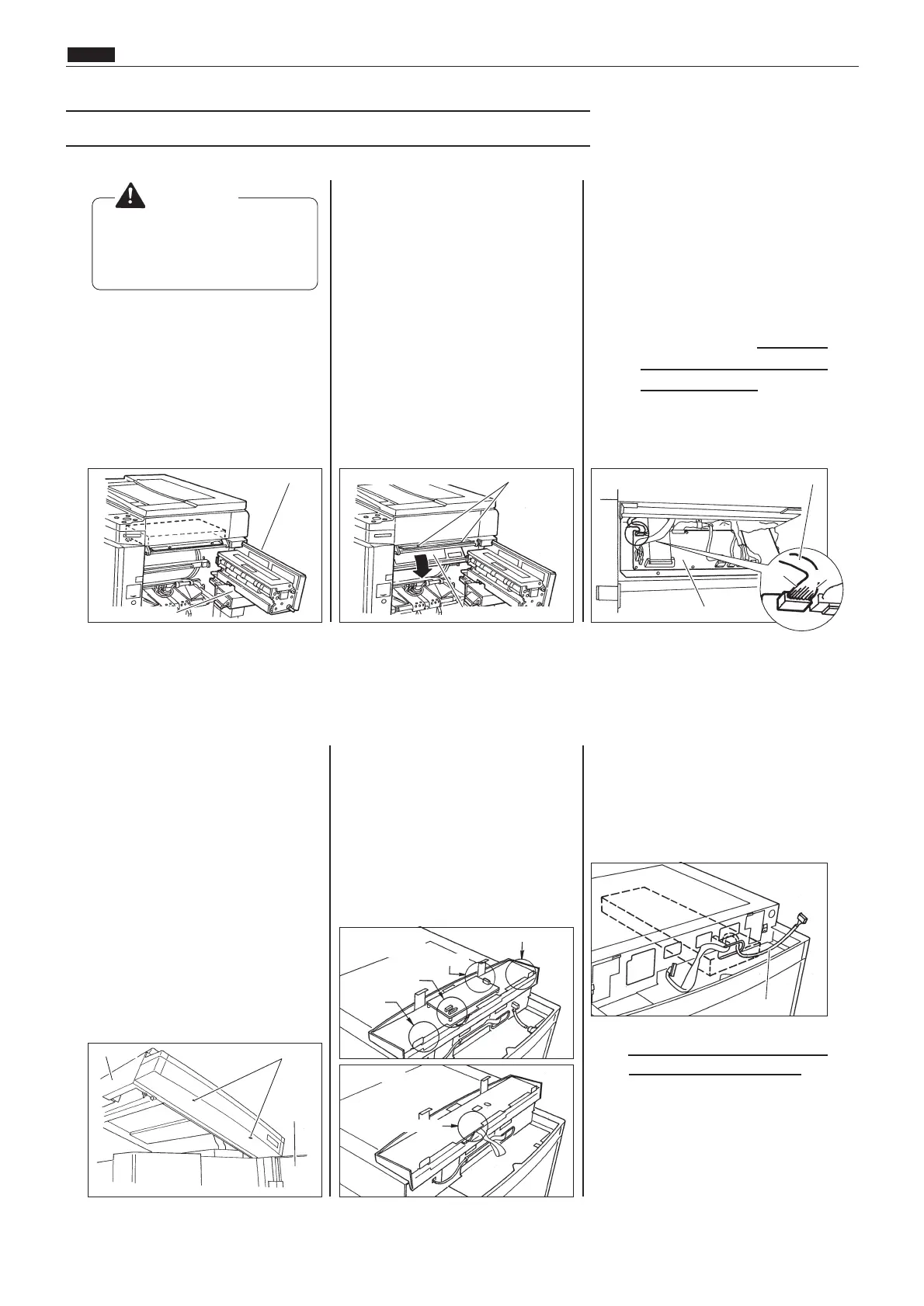
Push down the master ejection
box release lever. Then, keeping
the lever pushed down, pull the
master ejection box and top
blower fan out as far as they will
go.
2
Remove the two mounting
screws from the circuit board box.
Then lower the circuit board box
downward.
*Retain the two circuit board box
mounting screws, as they will
be reused later.
3
Insert the connector of the
KEYCARD COUNTER 3 cabled
wire unit (4) into CN20 in the
main circuit board.
*Orient the connector correctly.
Viewed from behind when it is
pointed at the main circuit board
prior to insertion, its red pin
should be on the left, and its
blue pin on the right.
¡ Remove the DUPRINTER
power cable's plug from the
outlet before install-
ing this unit.
WARNING
4
Open the front cover, lift up the top
cover release lever, and lift up the
top cover. Then remove the two
screws from the underside of the
operation panel.
*Retain the two operation panel
mounting screws, as they will
be reused later.
5
Slightly raise up the upper half of
the operation panel. Then discon-
nect the following connectors:
E type model (DP-43E, DP-33E,
DP-31E): the five connectors
shown below.
S type model (DP-43S, DP-33S,
DP-31S): the single connector
shown below.
6
Pass the cabled wire unit's other
connector through the opening in
the top of the circuit board box,
then out through the opening in
the end of the scanner unit.
7
Check once again that the
orientation of the connector that
was connected to the main circuit
board in step 3 is correct.
Provided it is, close the circuit
board box and secure the box with
the two mounting screws
removed earlier.
Master ejection box
Remove the two mounting screws from the circuit
board box
The circuit board box main circuit board
two screws
top cover
front cover
Top blower fan
red
blue
CN20
r
r
E type models
(total 5 connectors)
S type models
1 connector
1 connector
1 connector
1 connector
2 connectors