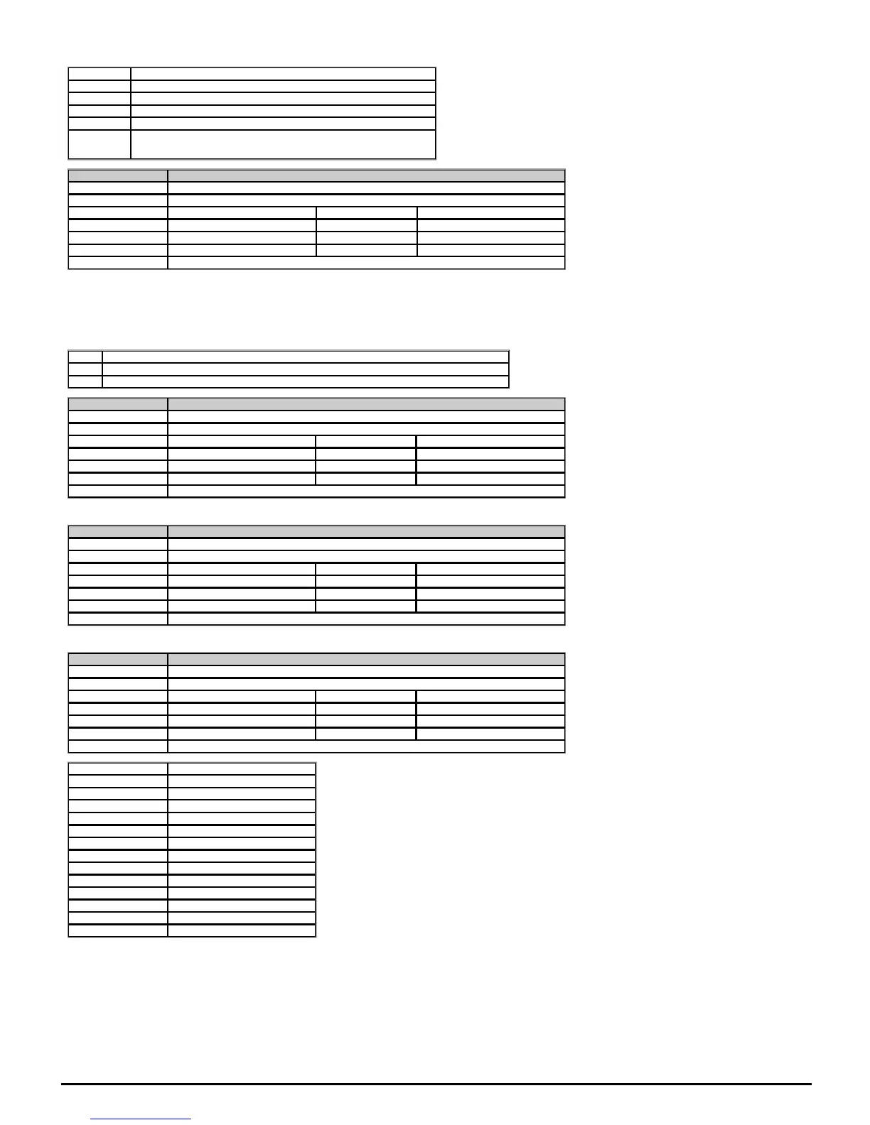
The "Input Level" is defined for the different modes in the table below.
Mode Input Level
Voltage (Input Voltage/ 10V) x 100.00%
0-20mA (Input Current / 20mA) x 100.00%
20-0mA (20mA - Input Current) / 20mA x 100.00%
4-20mA (Input Current - 4mA) / 16mA x 100.00%
20-4mA (20mA - Input Current) / 16mA x 100.00%
Parameter 07.002 Analog Input 2
Short description Displays the value of analog input 2
Mode Open‑loop
Minimum -100.00 Maximum 100.00
Default Units %
Type 16 Bit Volatile Update Rate 4ms
Display Format Standard Decimal Places 2
Coding RO, FI, ND, NC, PT
See AnalogI/O.
Voltage mode: This input is a unipolar voltage 0-10V.
Digital mode: This input can also be configured as a digital input in which case this parameter will indicate 0.00% or 100.00% depending on the state of the input.
The "Input Level" is defined for the different modes in the table below.
Mode Input Level
Voltage (Input Voltage/ 10V) x 100.00%
Digital 0.00% (corresponds to logical 0 if less than 9V) or 100.0% (corresponds to logical 1 if more than 11V)
Parameter 07.004 Stack Temperature
Short description Displays the temperature currently being measured on the heat sink
Mode Open‑loop
Minimum -250 Maximum 250
Default Units °C
Type 16 Bit Volatile Update Rate Background write
Display Format Standard Decimal Places 0
Coding RO, ND, NC, PT
This parameter displays the temperature currently being measured on the heat sink. This is used as part of the drive thermal model, see DriveOver-temperatureAlarm (10.018) for further details.
Parameter 07.005 Auxiliary Temperature
Short description Displays the temperature currently being measured on the power system
Mode Open‑loop
Minimum -250 Maximum 250
Default Units °C
Type 16 Bit Volatile Update Rate Background write
Display Format Standard Decimal Places 0
Coding RO, ND, NC, PT
This parameter displays the temperature currently being measured on the power system on large frames. This is used as part of the drive thermal model.
Parameter 07.007 Analog Input 1 Mode
Short description Defines the mode of analog input 1
Mode Open‑loop
Minimum -6 Maximum 6
Default 6 Units
Type 8 Bit User Save Update Rate Background read
Display Format Standard Decimal Places 0
Coding RW, TE
Value Text
-6 4-20.S
-5 20-4.S
-4 4-20.L
-3 20-4.L
-2 4-20.H
-1 20-4.H
0 0-20
1 20-0
2 4-20.tr
3 20-4.tr
4 4-20
5 20-4
6 Volt
See AnalogInput1 (07.001).
The table below gives all the possible analog input modes.
In 4-20mA and 20-4mA current input modes the software detects a current input less than 3mA as a current loop loss and initiates an action depending on the mode set in the table below.

 Loading...


