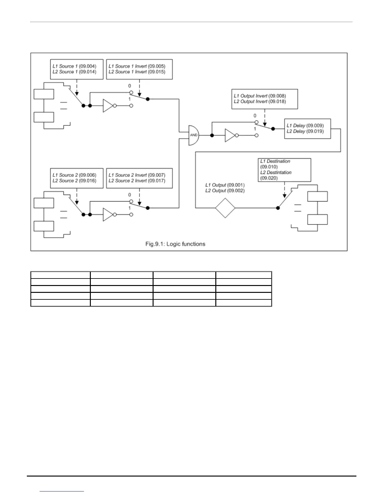
Logic functions
The logic functions are always active even if the sources and destinations are not routed to valid parameters. If the sources are not valid parameters
then the source values are taken as 0. The update rate for each of the logic functions is always 4ms
The logic function consists of an AND gate with inverters on each input and an inverter on the output. Some of the other standard logic functions can be
produced as shown in the table below.
Logic function Source 1 Invert Source 2 Invert Output Invert
AND 0 0 0
NAND 0 0 1
OR 1 1 1
NOR 1 1 0
A delay function is provided at the output of the logic functions. If LogicFunction1Delay (09.009) or LogicFunction2Delay (09.019) is positive then the
output does not become 1 until the input to the delay has been at 1 for the delay time. If LogicFunction1Delay (09.009) or LogicFunction2Delay
(09.019) is negative then the output remains at 1 until the input to the delay has been 0 for the delay time.

 Loading...


