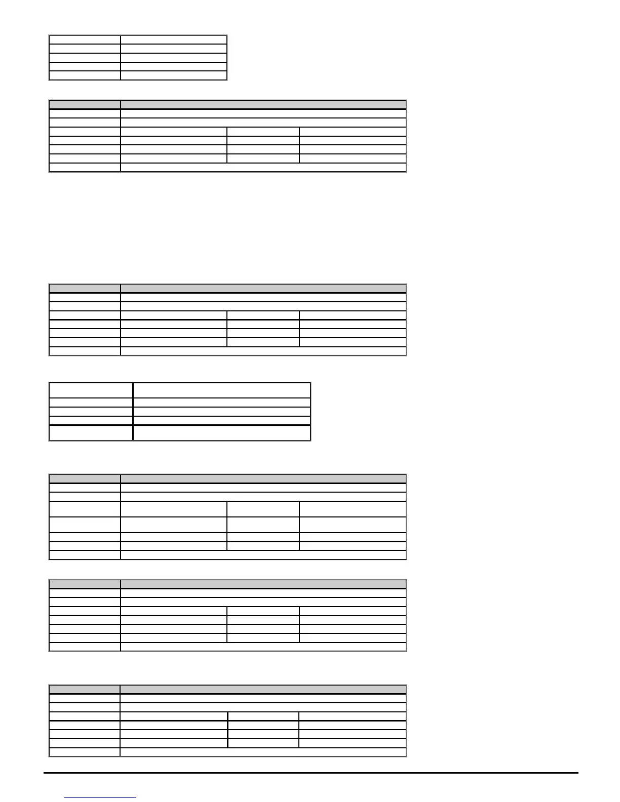
Value Text
0 0.5
1 1.0
2 2.0
3 4.0
See OutputPhaseLossDetectionEnable (06.059).
Parameter 06.059 Output Phase Loss Detection Enable
Short description Set to 1 to enable output phase loss detection
Mode Open‑loop
Minimum 0 Maximum 1
Default 0 Units
Type 1 Bit User Save Update Rate Background read
Display Format Standard Decimal Places 0
Coding RW
Output phase loss detection can be used to detect a disconnected motor phase if OutputPhaseLossDetectionEnable (06.059) is set to a non-zero value.
0: Disabled
Output phase loss detection is not active.
1: Enabled
A test is carried out each time the drive is enabled to run to check if all three phases are connected. If the test fails an OutPhaseLoss.X trip is initiated where X indicates which phase is not
connected (1 = U, 2 = V, 3 = W). It should be noted that this test is not carried out in Open-loop mode if "catch a spinning motor is enabled (i.e. CatchASpinningMotor (06.009) > 0).
A test is also carried out while the drive is running. If the drive output frequency is above 4Hz and a phase is disconnected for the time specified by OutputPhaseLossDetectionTime (06.058)
then a OutPhaseLoss.4 trip is initiated. It should be noted that if the motor is operating at high speed and flux weakening is active so that the magnetising current is below half the rated level
then output phase loss will not be detected. If the motor is heavily loaded when a phase is disconnected it is likely that the motor will stall and the drive output frequency may fall below 4Hz
before output phase loss is detected.
Parameter 06.060 Standby Mode Enable
Short description Set to 1 enable standby mode
Mode Open‑loop
Minimum 0 Maximum 1
Default 0 Units
Type 1 Bit User Save Update Rate Background read
Display Format Standard Decimal Places 0
Coding RW
If StandbyModeEnable (06.060) = 1 then the drive will go into the standby power state 20 seconds after the last key press and whenever DriveActive (10.002) = 0. In this state the LED on the
front of the drive flashes 0.25s on and 2s off. And the following actions are taken as defined by the StandbyModeMask (06.061). Actions are enabled by setting the appropriate bit to 1.
Standby Mode Mask
(06.061) bits
Action
0 NA
1 Instruct all keypads to go into their standby state
2 NA
3
Instruct the option module in option slot 1 to go into the standby
power state
Because of the limited number of segments on drives with an LED display, these drives will indicate the parameter value as a decimal value rather
than a binary value.
Parameter 06.061 Standby Mode Mask
Short description Defines the behaviour of standby mode
Mode Open‑loop
Minimum
0
(Display: 0000)
Maximum
15
(Display: 1111)
Default
0
(Display: 0000)
Units
Type 8 Bit User Save Update Rate Background read
Display Format Binary Decimal Places 0
Coding RW
See StandbyModeEnable (06.060).
Parameter 06.071 Slow Rectifier Charge Rate Enable
Short description Set to 1 to reduce the charge rate of the d.c. bus
Mode Open‑loop
Minimum 0 Maximum 1
Default 0 Units
Type 1 Bit User Save Update Rate Background read
Display Format Standard Decimal Places 0
Coding RW
For Frame size 07 and larger, which use a d.c. link charge system based on a half controlled thyristor input bridge, the rate at which the d.c. link is charged can be reduced by setting
SlowRectifierChargeRateEnable (06.071) to one. This will reduce the charging current which may be required if significant additional capacitance is added to the d.c. link to prevent rupturing
of input fuses.
Parameter 06.073 Braking IGBT Lower Threshold
Short description Defines the lowest level of the d.c. bus voltage where the braking IGBT becomes active
Mode Open‑loop
Minimum −VM_DC_VOLTAGE_SET Maximum VM_DC_VOLTAGE_SET
Default See exceptions below Units V
Type 16 Bit User Save Update Rate Background
Display Format Standard Decimal Places 0
Coding RW, VM, RA

 Loading...


