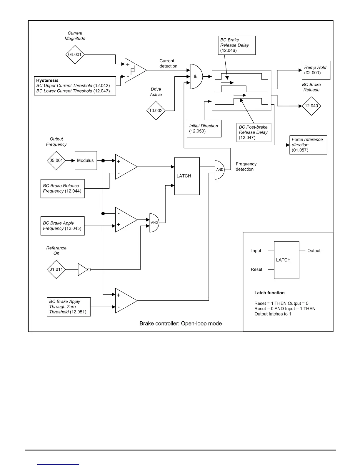
Current detection
The CurrentMagnitude (04.001) is compared to an upper and lower threshold by a comparator with hysteresis to give torque present and driveoutputopencircuit detection functions respectively.
BCLowerCurrentThreshold (12.043) and BCUpperCurrentThreshold (12.042) are given as a percentage of MotorRatedCurrent (05.007). BCUpperCurrentThreshold (12.042) should be set to
the current level that indicates that there is magnetising current and sufficient torque producing current in the motor to deliver the required amount of torque when the brake is released. The output of
the comparator remains active after this level has been reached unless the current subsequently falls below BCLowerCurrentThreshold (12.043) which should be set to the required level to detect
the condition where the motor has been disconnected from the drive. If BCLowerCurrentThreshold (12.043) ≥ BCUpperCurrentThreshold (12.042) then the upper threshold applies with a
hysteresis band of 0. If BCLowerCurrentThreshold (12.043) = BCUpperCurrentThreshold (12.042) = 0 then the output of the comparator is always one.
Frequency detection
The frequency comparator is used on starting, to detect when the motor frequency has reached a level where the motor can produce the required amount of torque to ensure that the motor rotates in
the demanded direction when the brake is released. BCBrakeReleaseFrequency (12.044) should be set to a level slightly above the motor slip frequency that is likely to occur under the highest
expected load that is applied to the motor when the brake is released.
The brake apply frequency threshold is used to ensure that the brake is applied before the motor frequency reaches zero and to prevent the motor rotating (in the reverse direction due to an
overhauling load for example) during the brake apply time. If the frequency falls below BCBrakeApplyFrequency (12.045), but the motor is not required to stop (i.e. reversing direction without
stopping) then ReferenceOn (01.011) will be one, and so the brake is not applied. This prevents the brake from activating and de-activating as the motor passes through zero speed. If the frequency
falls below BCBrakeApplyFrequency (12.045) and ReferenceOn (01.011) = 0 then the brake will be applied.
Brake Release
When both Current detection and Frequency detection conditions are met, the ramp is held and the brake released after the BCBrakeReleaseDelay (12.046). When the brake is released, the ramp
is held for a further period ( BCPost-brakeReleaseDelay (12.047) ) after which the ramp is released.
Brake controller sequence
The brake controller sequence is shown for forward movement in the diagram below.

 Loading...


