2/2
6. Electrical parts
63050
63050
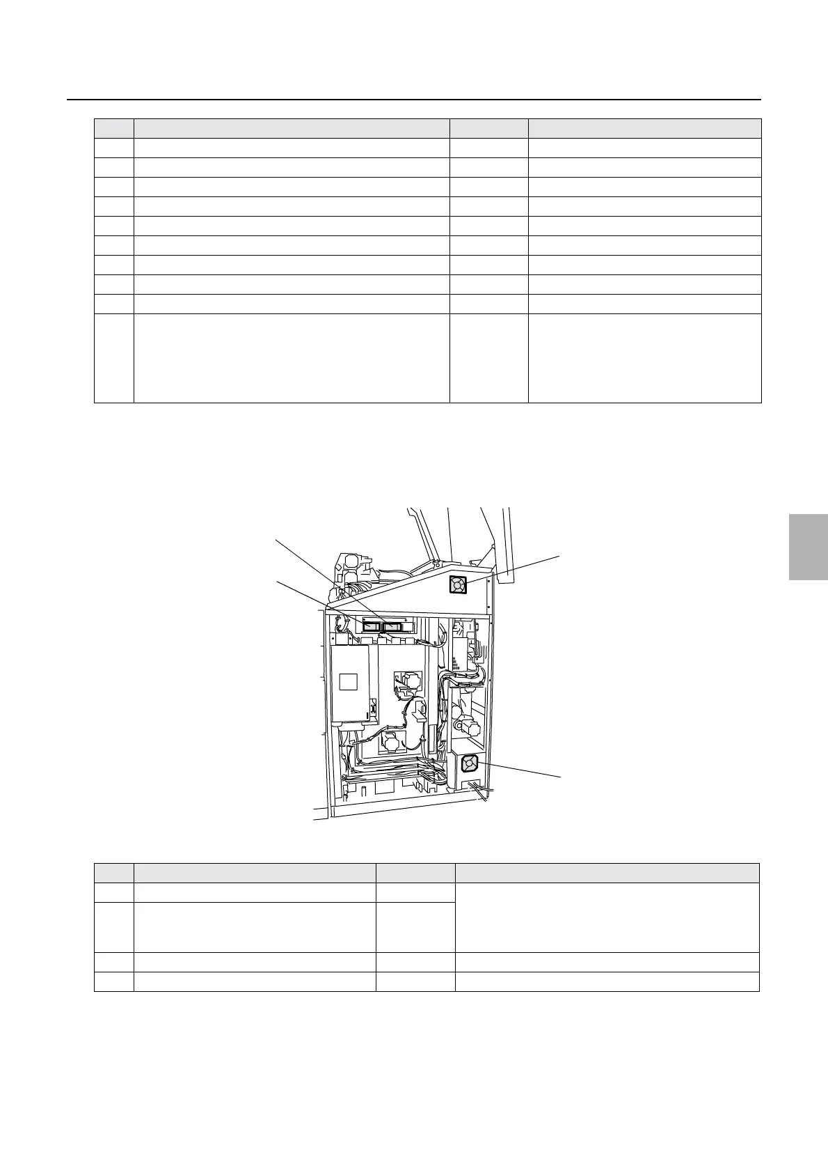
Position of electrical parts (printer section)
*1. When LS1, 2, 3, and 5 are turned off, all the motors in the printer stop.
In addition, the control signals of laser is cut off and laser light is not output from the laser unit.
*2. For the operation status of each interlock switch, see
☞Operation of the interlock switches (3521).
!
!!
! Position (back face)
Printer main body (back face)
5 Interlock Switch (Printer Top Cover)
*2
LS1
*1
6 Laser control box cooling fan 1 FAN7 Blowing (the fan is always ON.)
7 Inner thermosensor TH1
8 Paper magazine lamp B/C L1
9 Paper magazine lamp A L2
10 Counter CO Option
11 Interlock switch (printer door 4) LS5
*1
12 Buzzer BZ1
13 Control box cooling fan 4 FAN6 Intake (The fan is always on.)
14 Fuse (3.15 A/ 200 V) F5 • 200 V power supply protection
• See the illustration.
• The external AC power supply
protected with fuse F5 can be used up to
1.5A.
No. Name Symbol Remarks
1 Laser unit cooling fan 1 FAN8 • When the laser unit temperature sensor exceeds 30°C,
the laser unit cooling fans 1 and 2 turn on.
• When the laser unit temperature sensor is 27°C or
lower, the laser unit cooling fans 1 and 2 turn off.
2 Laser unit cooling fan 2 FAN9
3 Control box cooling fan 1 FAN2 Exhaust (The fan is always on.)
4 Paper advance section cooling fan 1 FAN5 Intake (The fan is always on.)
No. Name Symbol Remarks
4
3
2
1
G085245
Distributed by: minilablaser.com