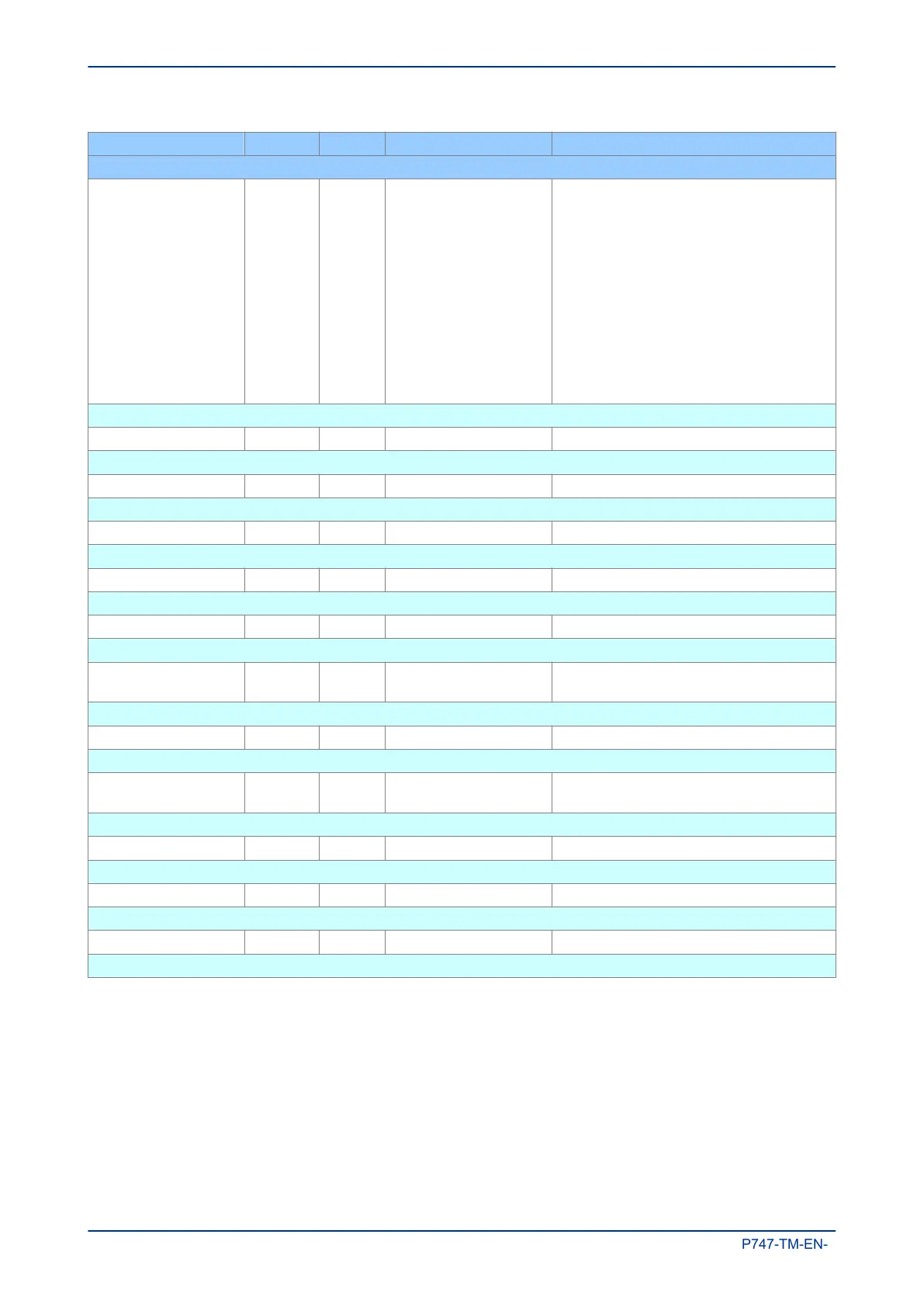
Menu Text Col Row Default Setting Available Options
Description
I>1 Function 35 82 IEC S Inverse
0 = Disabled
1 = DT (DT)
2 = IEC S Inverse (TMS)
3 = IEC V Inverse (TMS)
4 = IEC E Inverse (TMS)
5 = UK LT Inverse (TMS)
6 = Rectifier (TMS)
7 = RI (K)
8 = IEEE M Inverse (TD)
9 = IEEE V Inverse (TD)
10 = IEEE E Inverse (TD)
11 = US Inverse (TD)
12 = US ST Inverse (TD)
This setting determines the tripping characteristic for the first stage overcurrent element.
I>1 Current Set 35 84 1.0*I5 From 0.08*I5 to 4.0*I5 step 0.01*I5
This sets the pick-up threshold for the first stage overcurrent element.
I>1 Time Delay 35 85 1 From 0 to 100 step 0.01
This sets the DT time delay for the first stage overcurrent element.
I>1 TMS 35 86 1 From 0.025 to 1.2 step 0.025
This is the Time Multiplier Setting to adjust the operate time of IEC IDMT curves.
I>1 Time Dial 35 87 1 From 0.01 to 100 step 0.01
This is the Time Multiplier Setting to adjust the operate time of IEEE/US IDMT curves.
I>1 K (RI) 35 88 1 From 0.1 to 10 step 0.05
This setting defines the TMS constant to adjust the operate time of the RI curve.
I>1 Reset Char 35 89 DT
0 = DT
1 = Inverse
This setting determines the type of Reset characteristic used for the IEEE/US curves.
I>1 tRESET 35 8A 0 From 0 to 100 step 0.01
This setting determines the Reset time for the Definite Time Reset characteristic.
I>2 Function 35 8B Disabled
0 = Disabled
1 = DT (DT)
This setting determines the tripping characteristic for the second stage overcurrent element.
I>2 Current Set 35 8D 1.0*I5 From 0.08*I5 to 10.0*I5 step 0.01*I5
This sets the pick-up threshold for the second stage overcurrent element.
I>2 Time Delay 35 8E 1 From 0 to 100 step 0.01
This sets the DT time delay for the second stage element.
Terminal 6 35 A1
This column contains overcurrent settings for Terminal 6
Chapter 5 - Protection Functions MiCOM P747
120 P747-TM-EN-1

 Loading...


