The output relay board can be provided together with the power supply board as a complete assembly, or
independently for the purposes of relay output expansion.
In the above figure, you can see the two cut-out locations in the board. These can be removed to allow
power supply components to protrude when coupling the output relay board to the power supply board. If the
output relay board is to be used independently, these cut-out locations remain intact.
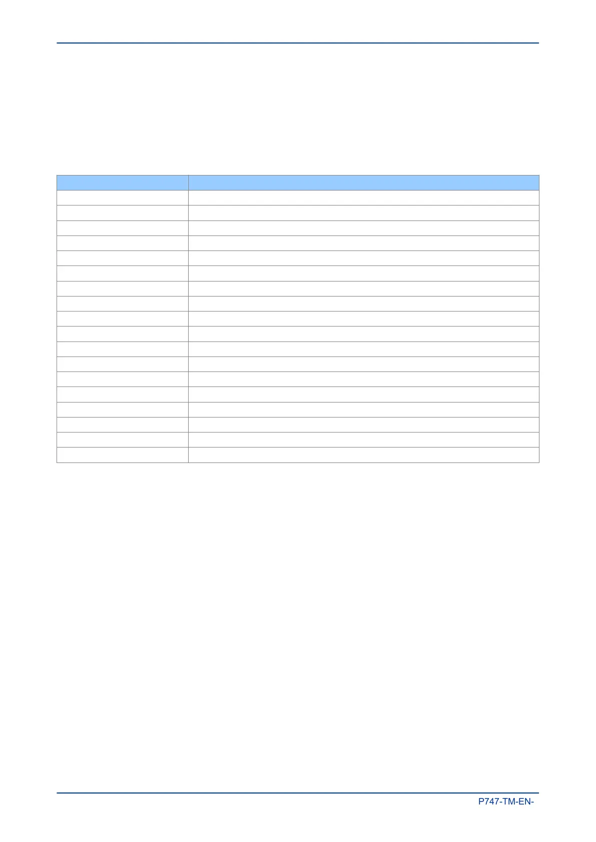
The terminal numbers are as follows:
Terminal Number Output Relay
Terminal 1 Relay 1 NO
Terminal 2 Relay 1 NO
Terminal 3 Relay 2 NO
Terminal 4 Relay 2 NO
Terminal 5 Relay 3 NO
Terminal 6 Relay 3 NO
Terminal 7 Relay 4 NO
Terminal 8 Relay 4 NO
Terminal 9 Relay 5 NO
Terminal 10 Relay 5 NO
Terminal 11 Relay 6 NO
Terminal 12 Relay 6 NO
Terminal 13 Relay 7 changeover
Terminal 14 Relay 7 common
Terminal 15 Relay 7 changeover
Terminal 16 Relay 8 changeover
Terminal 17 Relay 8 common
Terminal 18 Relay 8 changeover
Chapter 3 - Hardware Design MiCOM P747
48 P747-TM-EN-1

 Loading...


