GE
P
ART NUMBER FN091065, REVISION 2 VS5 N AND VS6 N SERVICE MANUAL
8-46 Section 8-3 - Control Console Components Replacement Procedures
PRELIMINARY
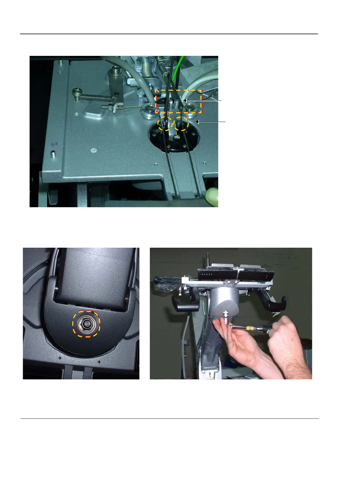
5.) Remove two brake lever retaining screws - Figure 8-57 and remove the Gas Spring lever.
6.) To release the Keyboard Interface Assembly from the lower support arm, unscrew the retaining bolt
from below the Keyboard Interface Assembly using a box spanner - Figure 8-58.
7.) Holding the Keyboard Interface Assembly base with both hands and pressing the swivel lever
Figure 8-57 Up-Down Lever Separated from Gas Spring Cable Lever
Figure 8-58 Keyboard Interface Assembly - Location of Retaining Bolt
Two Brake Lever Retaining Screws
Up-Down Lever
Separated from Gas Spring Cable Lever

 Loading...


