D
IRECTION FR091521, REVISION 1 VIVID S60N/VIVID S70N BASIC SERVICE MANUAL
Chapter 3 - System Setup 3-19
PRELIMINARY
Section 3-5
Completing the Setup
3-5-1 Purpose of this Section
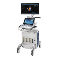
This section describes how to complete the setup of the Vivid™ S60/Vivid™ S70.
3-5-2 System Specifications
3-5-2-1 System Requirements Verification
• Verify that the site meets the requirements listed in Chapter 2.
(See: Facility Needs on page 2 - 6.)
• Verify that the specifications below do not conflict with any on-site conditions.
3-5-2-2 Physical Dimensions
3-5-2-3 Mass with Monitor and Peripherals
3-5-2-4 Acoustic Noise Level
Less than 55 dB(A) at 20 degrees Celsius, measured in the operators head position, 20 cm in front of
the keyboard’s right corner, at 1.30 m above the floor, and in a distance of 1 meter at all four sides, 1
meter above the floor.
3-5-3 Electrical Specifications
3-5-3-1 Verification of the Vivid™ S60/Vivid™ S70 Voltage Setting
Verify that the mains voltage specified for the Vivid™ S60/Vivid™ S70 is available on-site.
The voltage setting for the Vivid™ S60/Vivid™ S70 is found on a label near the Mains Power Circuit
Breaker on the rear of the Vivid™ S60/Vivid™ S70.
3-5-3-2 Electrical Specifications for the Vivid™ S60/Vivid™ S70
In the table below, the electrical specifications for Vivid™ S60/Vivid™ S70 includes monitor and on
board peripherals.
Table 3-10 Physical Dimensions of Vivid™ S60/Vivid™ S70 with Monitor and Peripherals
in Transportation Position
Height Width Depth Unit
104 75 77 cm
40.95 29.50 30.30 Inches
Table 3-11 Mass of Vivid™ S60/Vivid™ S70 with Monitor, without Probes and Peripherals
Model Mass [KG] Mass [LBS]
Vivid™ S60/Vivid™ S70 75 165
Connecting a Vivid™ S60/Vivid™ S70 to the wrong voltage
level will most likely destroy it.

 Loading...