D
IRECTION FR091521, REVISION 1 VIVID S60N/VIVID S70N BASIC SERVICE MANUAL
8-48 Section 8-3 - Control Console Components - Replacement Procedures
PRELIMINARY
8-3-7 Operator Panel GE Logo 40 mm Replacement Procedure
NOTE: The Operator Panel is supplied without the GE logos fitted one on each side. When replacing the
Operator Panel, it is necessary to order the Operator Panel and in addition, two GE logos (supplied as
a separate part, see below).
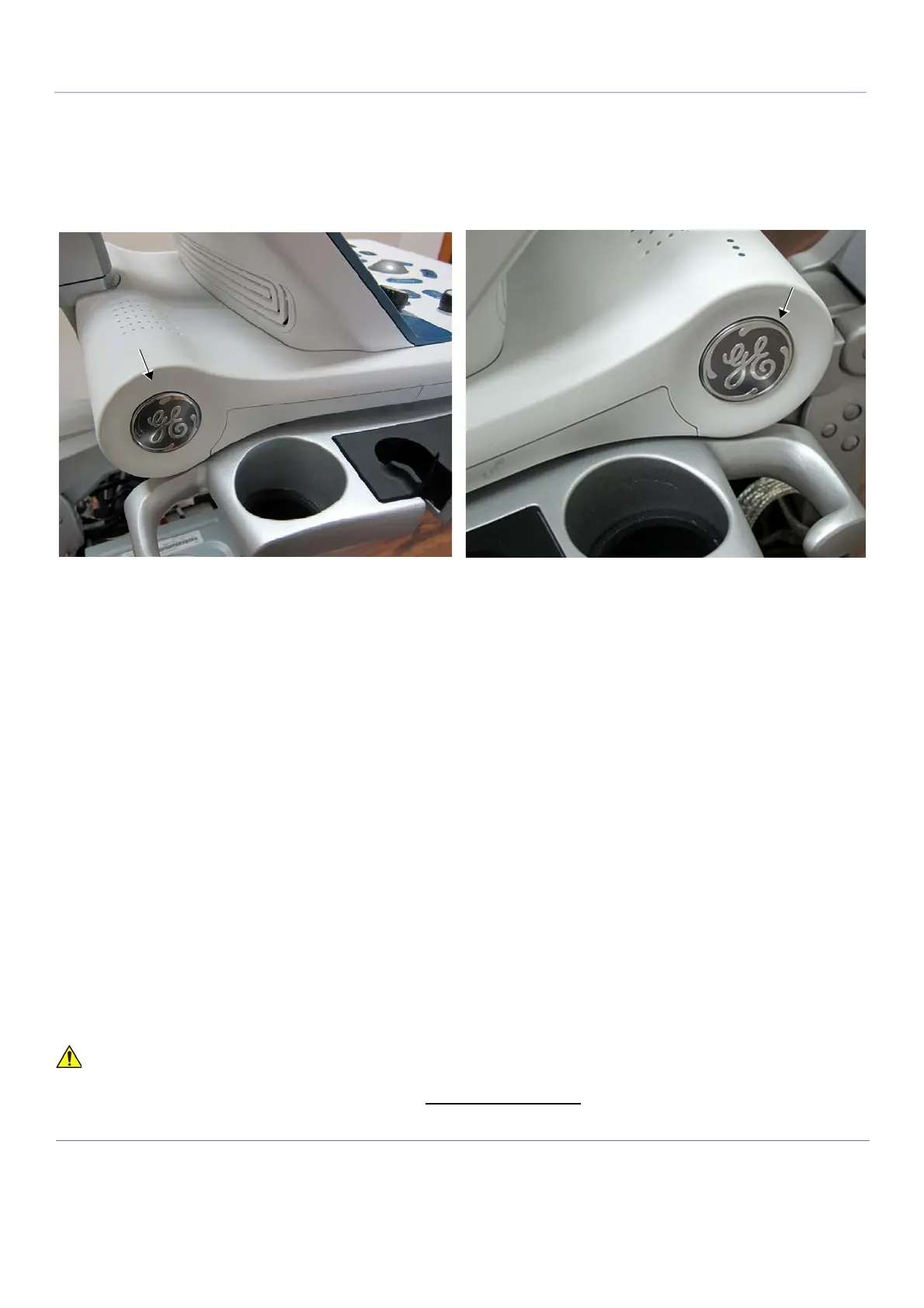
One GE logo is located on either side of the Operator Panel as shown in Figure 8-54.
8-3-7-1 Tools
No special requirements
8-3-7-2 GE Logo Removal Procedure
NOTE: In the event that only the GE Logo is damaged (i.e. the Operator Panel is not being replaced), it is
necessary to remove the old logo from the OPIO, as described below.
1) Using a blunt non-metallic instrument, gently raise one edge of the damaged GE logo.
2) Carefully prize the logo away from the Operator Panel.
8-3-7-3 GE 40 mm Logo Installation Procedure
1) Prior to adhering the logo, ensure the outer surface of the Operator Panel is clean, dry, and free of
particles.
2) Remove the GE logo from it’s packing.
3) Peel back the plastic protective outer layer from the logo and remove it to expose the adhesive
surface.
4) Carefully place the logo in position ensuring that the letters are correctly oriented (upright), straight
and parallel to the inlaid impression on the side of the Operator Panel.
5.) Carefully applying even pressure around the perimeter
of the logo to ensure a firm adhesion.
6.) Repeat the above steps to adhere a GE logo to the opposite side of the Operator Panel.
Figure 8-54 GE Logo - Located on Left and Right Side of Operator Panel
Refer to Table 9-11 on page 9-10
Do not apply pressure to the center of the logo while adhering it to the Operator Panel as this will
damage the part.

 Loading...


