D
IRECTION FR091521, REVISION 1 VIVID S60N/VIVID S70N BASIC SERVICE MANUAL
Chapter 10 - Care and Maintenance 10-21
PRELIMINARY
NOTE: For more information, refer to the safety analyzer’s user manual that will be used to perform the tests.”
The maximum allowable limit for chassis source leakage is shown in:
• Table 10-11 on page 10-17
or
• Table 10-12 on page 10-17
as Chassis/Enclosure Leakage.
10-6-6-3 Data Sheet for Enclosure/Chassis Leakage Current
Table 10-15 below shows a typical format for recording the enclosure/chassis leakage current.
Measurements should be recorded from multiple locations for each set of test conditions.
The actual location of the test probe may vary by Ultrasound system.
NOTE: Values in italics font are given as examples only.
Record all data in the Electrical safety tests log.
NOTE: Values in italics font are given as examples only.
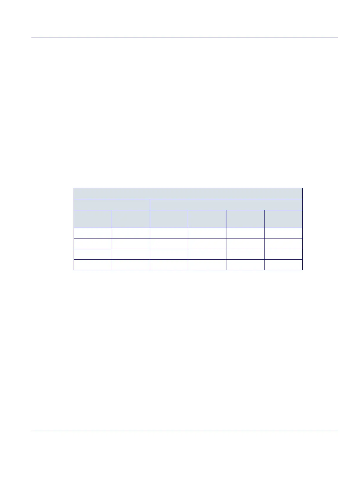
Table 10-15 Typical Data Format for Recording Enclosure/Chassis Leakage
Unit under test____________________________________ Date of test:_____________
Test Conditions Measurement/Test Point Location
System
Power
Grounding/
PE
Rear
Panel
Lower
Frame
Probe
Connector Main Handle
off closed
off open
on closed
on open

 Loading...


