D
IRECTION FR091521, REVISION 1 VIVID S60N/VIVID S70N BASIC SERVICE MANUAL
Chapter 5 - Components and Function (Theory) 5-21
PRELIMINARY
Section 5-9
Front End Unit
5-9-1 General Information
The Vivid™ S60/Vivid™ S70 Front End Unit is designed to support the cSound SW beam-forming
architecture for 128 channels.
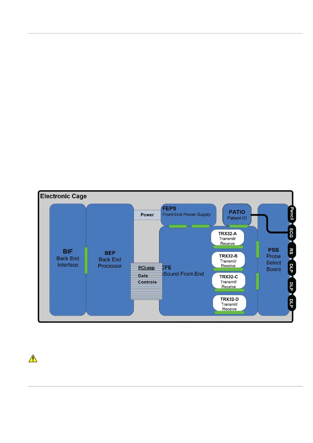
The Front End Unit, located in the door of the Electronic Cage (see Figure 5-20), comprises the
following modules:
- Front End Power Supply (FEPS)
See Front End Power Supply (FEPS) on page 5 - 22
- Control Front End (cFE) Module - includes four Transmit and Receive Modules (TRX32)
See Front End (cFE) Board on page 5 - 22 and Patient I/O Module on page 5-23.
- Probe Selector Module (PSB)
For interconnection of probes - see Probe Selection Board (PSB) on page 5-23
- Patient I/O Module (PATIO)
For a detailed description, see Patient I/O Module on page 5 - 23
NOTE: For Service Access to the Front End Unit modules, see Modules Accessed from the Front on page 5 - 14.
Figure 5-20 Front End Unit - Location of Components in Electronic Cage Assembly
WHEN OPENING AND CLOSING THE ELECTRONIC CAGE ASSEMBLY, TAKE CARE
NOT TO DAMAGE THE CABLES CONNECTED TO THE BEP.

 Loading...


