D
IRECTION FR091521, REVISION 1 VIVID S60N/VIVID S70N BASIC SERVICE MANUAL
Chapter 8 - Replacement Procedures 8-101
PRELIMINARY
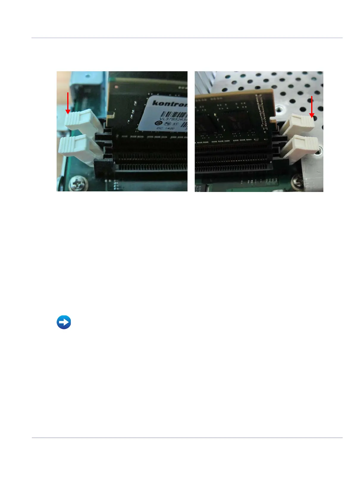
4.) Remove the Module Memory DDR circuit boards by pressing firmly downwards on the white
securing clips on the left and right sides respectively shown in Figure 8-126.
The circuit boards will be released as the clips open.
5.) Carefully grip the released circuit board on the left and right sides and slide it evenly upwards away
from the base connectors.
6.) Similarly, remove the second circuit board.
8-5-6-5 Module Memory DDR Installation Procedure
1.) Insert the replacement circuit board by sliding it into its appropriate slots - sliding the circuit board
gently and evenly downwards.
2.) As the circuit board reaches its “home” position, press firmly downward until the plastic securing
clips automatically engage to secure the circuit board.
3.) Repeat step 2 to insert the second circuit board.
4.) Return the Module Memory DDR cover to its position on the BEP and secure it with the 8 screws
previously removed.
5.) Reinstall the BEP:
6.) Turn ON the system and boot-up.
Figure 8-126 Removing the Module Memory DDR Circuit Boards
• BEP Installation Procedure on page 8 - 97

 Loading...


