D
IRECTION FR091521, REVISION 1 VIVID S60N/VIVID S70N BASIC SERVICE MANUAL
Chapter 8 - Replacement Procedures 8-61
PRELIMINARY
Section 8-4
Cables - Replacement Procedures
8-4-1 Keyboard and Monitor Cable Replacement Procedure
The Vivid™ S60/Vivid™ S70 system’s communication and power cables extend from the LCD Monitor
downwards, along the Articulated Arm Assembly to the Keyboard Interface Assembly, and finally to the
Back End Interface Board (BIF). The replacement procedures are carried out in stages, as described in
the sub-sections below.
NOTE: The following stages show the order in which cables are removed:
• LCD Monitor
• Keyboard assembly/OPIO
• Upper/Lower Arm Assembly
•BIF
8-4-1-1 Tools
Use the appropriate Phillips screwdriver, Allen key, diagonal side cutter, round punch, light hammer.
8-4-1-2 Time Required
120 min.
8-4-1-3 Preparation
Shut down the Vivid™ S60/Vivid™ S70 ultrasound unit, as described in Power Shut Down on page 4 - 7.
8-4-1-4 Keyboard and Monitor Cable Removal Procedure
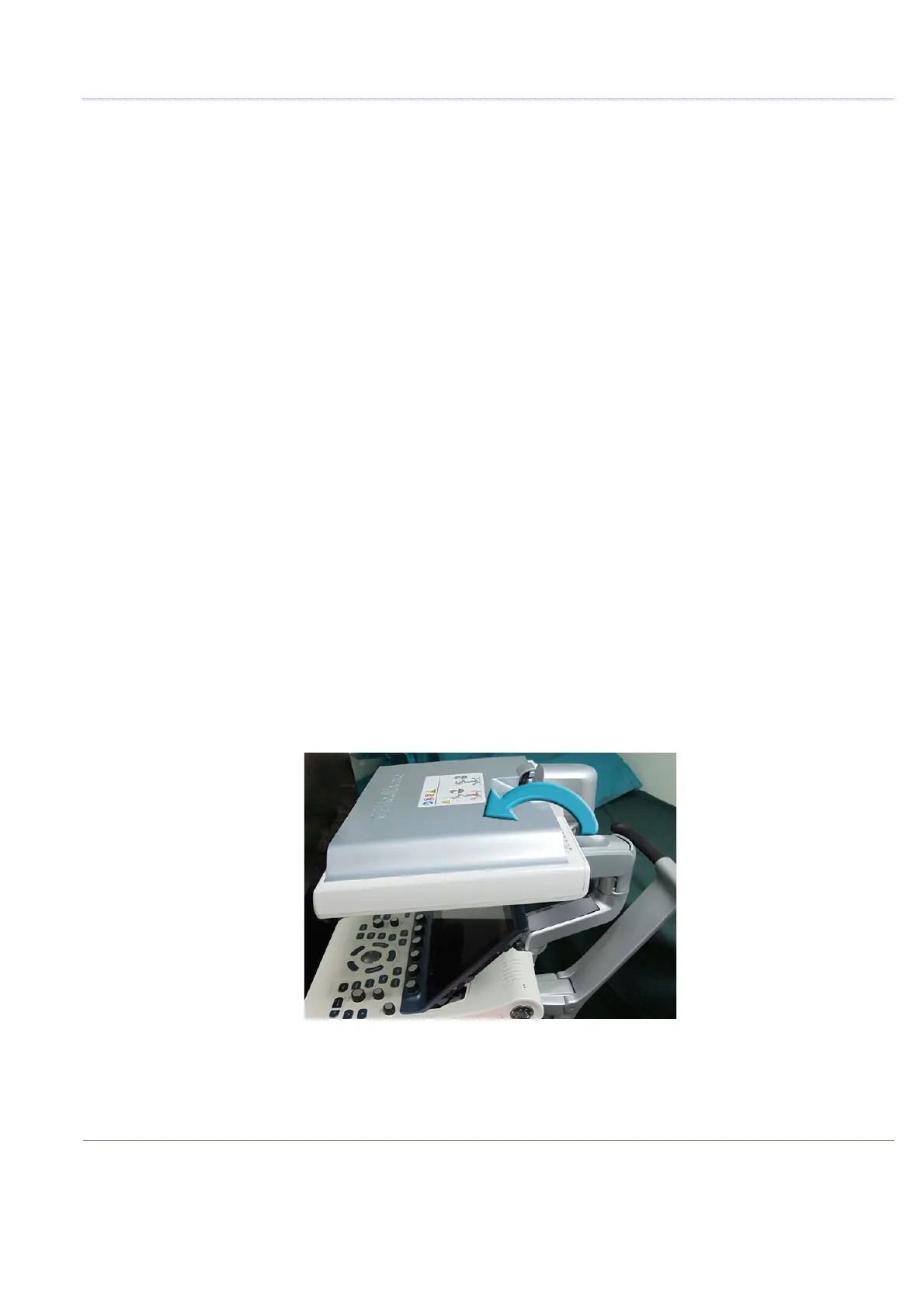
1.) Lock the articulated arm in position and fold the monitor to its maximum face-down position - see
Figure 8-71 below.
Refer to Table 9-20 on page 9-19.
Figure 8-71 Monitor Locked in Face-Down Position

 Loading...


