D
IRECTION FR091521, REVISION 1 VIVID™ S60N/VIVID™ S70N PROPRIETARY SERVICE MANUAL
5-20 Section 5-8 - Internal and External Input/Output
PRELIMINARY
Section 5-8
Internal and External Input/Output
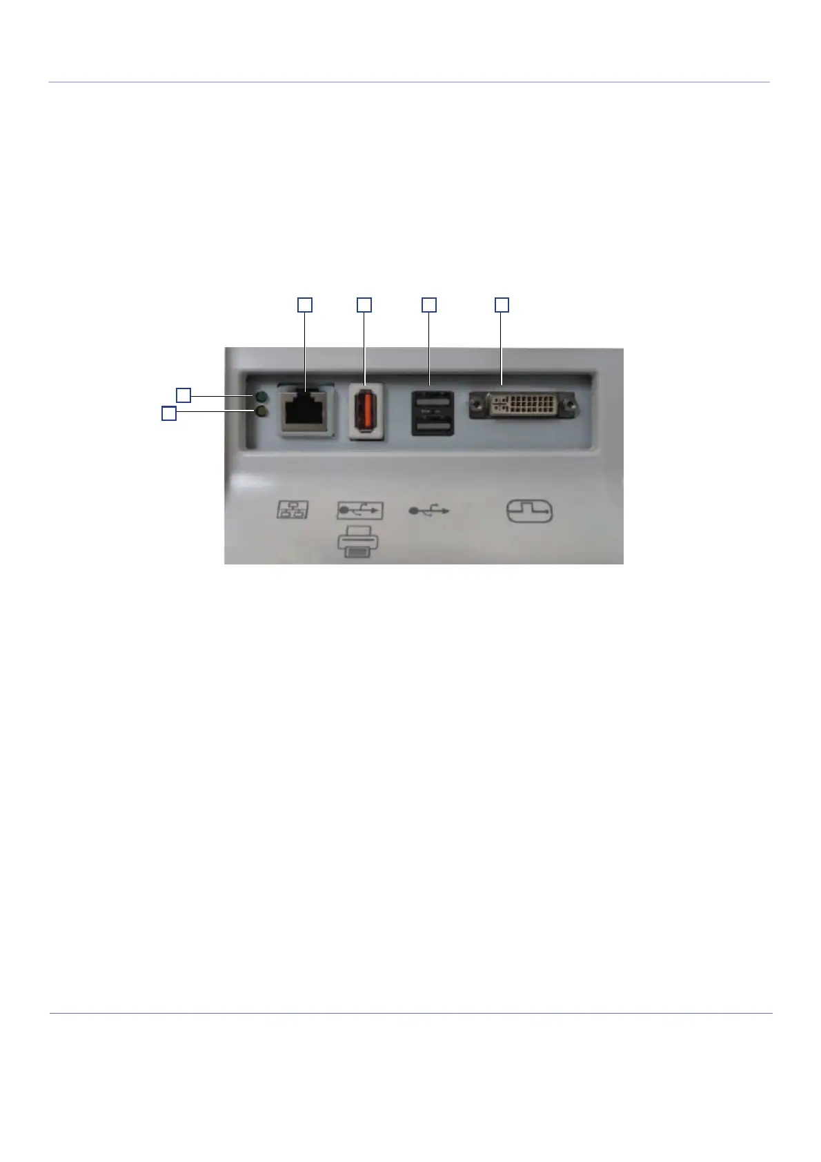
The Vivid™ S60/Vivid™ S70 ultrasound scanner has a connection panel (located at the rear of the
electronic cage) that can host the connections illustrated below.
Figure 5-19 shows a view of the Vivid S60N/Vivid S70N ultrasound unit rear panel showing external
peripheral/accessory connectors.
1 Ethernet LAN connector — 1000 Base-TX Ethernet IEEE 802.3
2 Isolated USB connector (USB 1.0 only)
3 Dual USB connector
4 DVI-D Display OUT connector (DVI-I type with digital output only [DVDI-D])
5 LED - Network activity
6 LED - Network activity
Figure 5-19 View of the Vivid S60N/Vivid S70N Peripheral/Accessory Connector Panel

 Loading...


