D
IRECTION FR091521, REVISION 1 VIVID S60N/VIVID S70N BASIC SERVICE MANUAL
8-38 Section 8-3 - Control Console Components - Replacement Procedures
PRELIMINARY
8-3-4 Vivid™ S60/Vivid™ S70 Touch Screen Replacement Procedure
NOTE: The procedures below provide instructions for replacement of the Touch Screen.
For details on replacing the Touch Screen chassis, refer to Touch Screen Chassis Replacement
Procedure on page 8 - 147.
8-3-4-1 Tools
Phillips screwdriver and 7mm socket.
NOTE: When replacing the Touch Screen, if replacement of the Touch Screen Rotaries Board is also required,
it is also necessary to order this part (supplied separately). See Table 9-11 on page 9-10.
8-3-4-2 Time Required
20 min
8-3-4-3 Preparation
Shut down the Vivid™ S60/Vivid™ S70 ultrasound unit, as described in Power Shut Down on page 4 - 7.
8-3-4-4 Touch Screen Removal Procedure
1) Raise the console to the maximum up position.
Make sure it is aligned in the central position (not pulled to one side or the other).
2) Remove the following Touch Screen covers: service, rear:
Note: The Touch Screen Panel is fastened to the Touch Screen chassis by 4 screws (2 on each side).
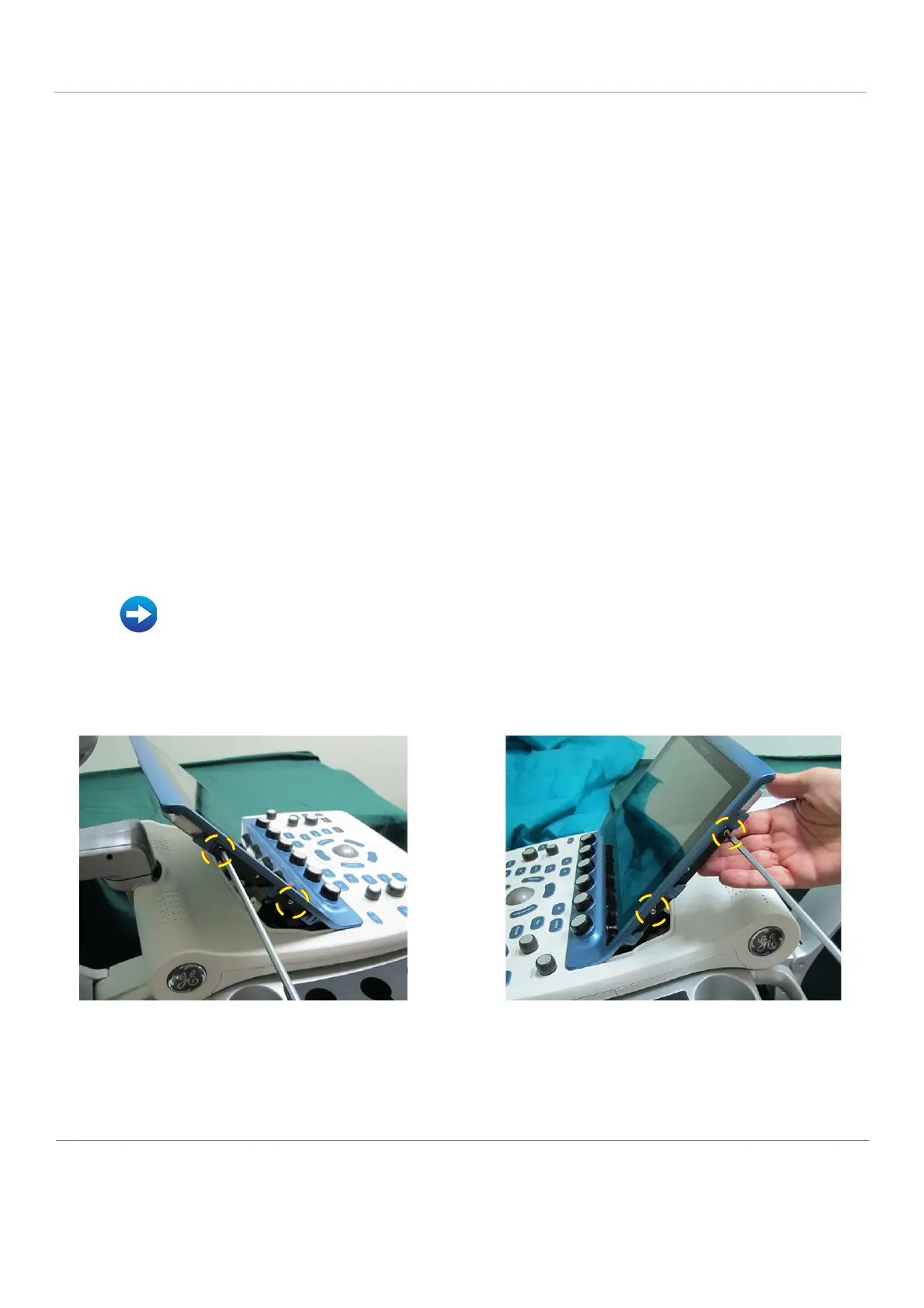
3) Remove the 2 securing screws on both the left and right sides of the Touch Screen - Figure 8-40.
Refer to Table 9-11 on page 9-10 (Touch Panel Assembly)
• Touch Screen Service Cover Removal Procedure on page 8 - 34
• Touch Screen Rear Cover Removal Procedure on page 8 - 36
Figure 8-40 Removing the Touch Screen Securing Screws

 Loading...


