D
IRECTION FR091521, REVISION 1 VIVID S60N/VIVID S70N BASIC SERVICE MANUAL
Chapter 5 - Components and Function (Theory) 5-3
PRELIMINARY
NOTE: For additional views of the system, see illustrations in Vivid™ S60/Vivid™ S70 System Design on page
5 - 4.
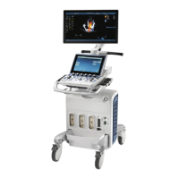
System operations are initiated by the user via the Operator Panel (that has ultrasound-specific buttons,
mode-dependent softkey buttons and an optional alphanumeric keyboard), and the Touch Screen.
NOTE: For a detailed description of Vivid™ S60/Vivid™ S70 system operating modes, refer to the Vivid™ S60/
Vivid™ S70 User Manual.
The Vivid™ S60N/Vivid™ S70N ultrasound scanner has a software beam-forming system.
Signal flow from the Probe Connector Panel, to the Front End (FE) Electronics, and to the Back End
Unit, are finally displayed on the monitor and peripherals.
In addition, the Vivid™ S60/Vivid™ S70 system enables acquisition of external ECG signals.
The ECG/Respiratory module, which supports acquisition of three bipolar ECG channels (leads I, II, III),
is incorporated in the cabinet cage assembly to provide ECG signals to synchronize cardiac ultrasound
image acquisition.
5-2-1-1 System Configuration and Software
System configuration is stored on a hard disk drive inside the Back End Unit.
At power up, all necessary software is loaded from the hard disk.
5-2-1-2 Electronics
The Vivid™ S60/Vivid™ S70 system internal electronics are divided into three:
• Front End Unit - see page 5 - 21
• Back End Unit - see page 5 - 24
• System Power Distribution - see page 5 - 25
Vivid™ S60/Vivid™ S70 system internal electronics comprise a single electronic cage (Figure 5-8) that
contains both the Front End Unit and the Back End Unit. The Interconnecting signals and power
distribution between the two sections are routed internally via two cables; boards are connected directly
to each other. All the interconnections to the monitors, operator keyboard and peripherals are via the
Backend Interface Board (BIF) which is fully shielded for EMC/EMI purposes.

 Loading...