7
────────────────────────────────────────────────────
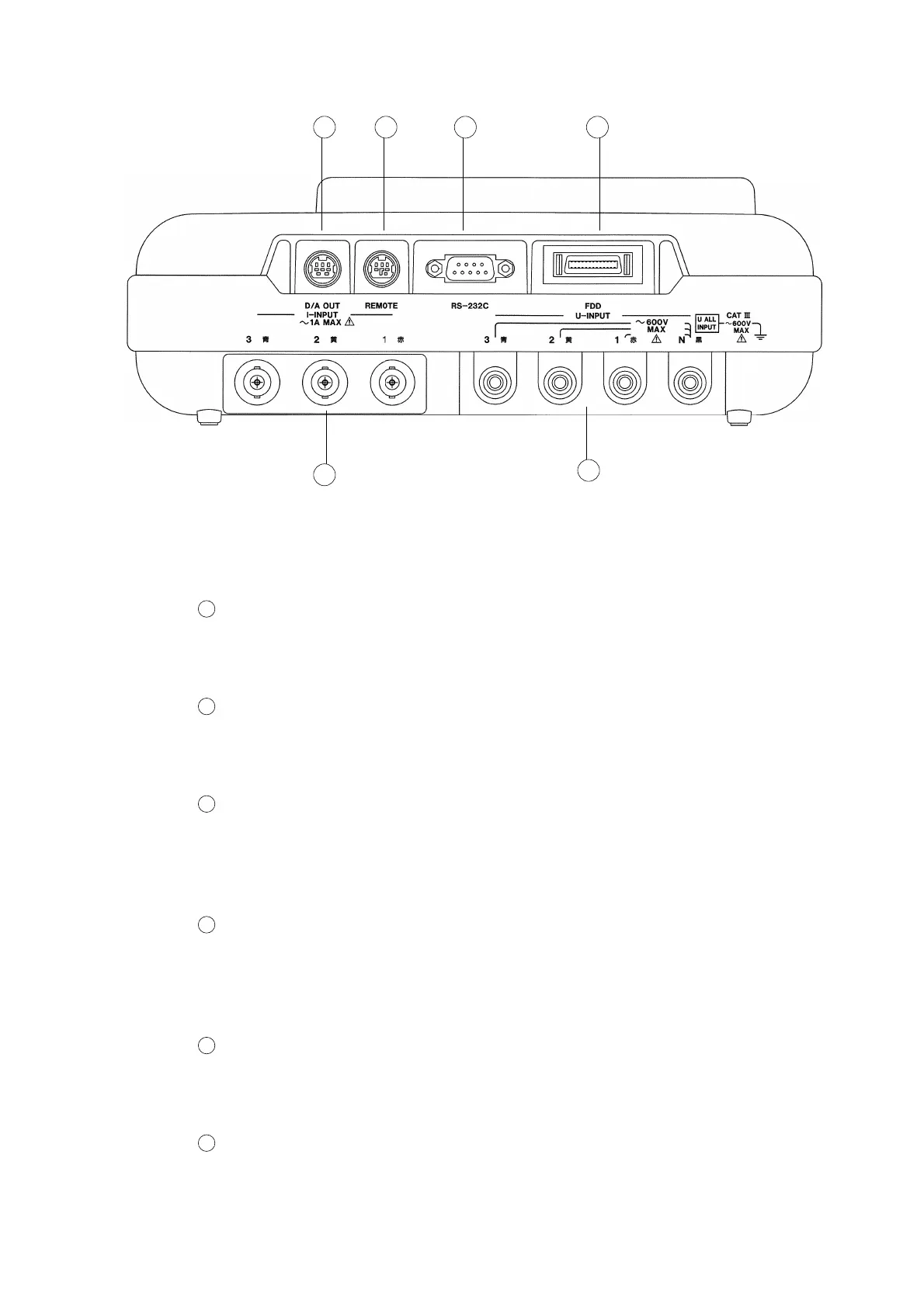
1.3 Names and Functions of Each Part
────────────────────────────────────────────────────
Connector Section
1
2
3
4
5
6
Voltage input connectors (U-INPUT)
Connect the 9438 VOLTAGE CORD provided with this power meter, in
accordance with the line to be tested.
Current input connectors (I-INPUT)
Connect the optional 9291/ 9298 CLAMP ON SENSOR in accordance with the
line to be tested, and then lock the connections securely.
D/A output connector (D/A OUT)
Connect the 9441 CONNECTION CABLE (for D/A OUTPUT) provided with
this power meter to this D/A output in order to obtain analog output from the
power meter.
External control connector (REMOTE)
Connect the optional 9440 CONNECTION CABLE (for External Control) to
this connector in order to control the start/stop of integrated or demand
measurement, printing, and the saving of data to floppy disk.
RS-232C interface connector (RS-232C)
This interface connector is used to connect a printer, personal computer or
modem to this power meter.
FDD unit connector (FDD)
Connect the optional 9595 FDD UNIT to this connector in order to save
measurement data or save/load settings.