3.7 Address Configuration
A3-46
ME0384-4A
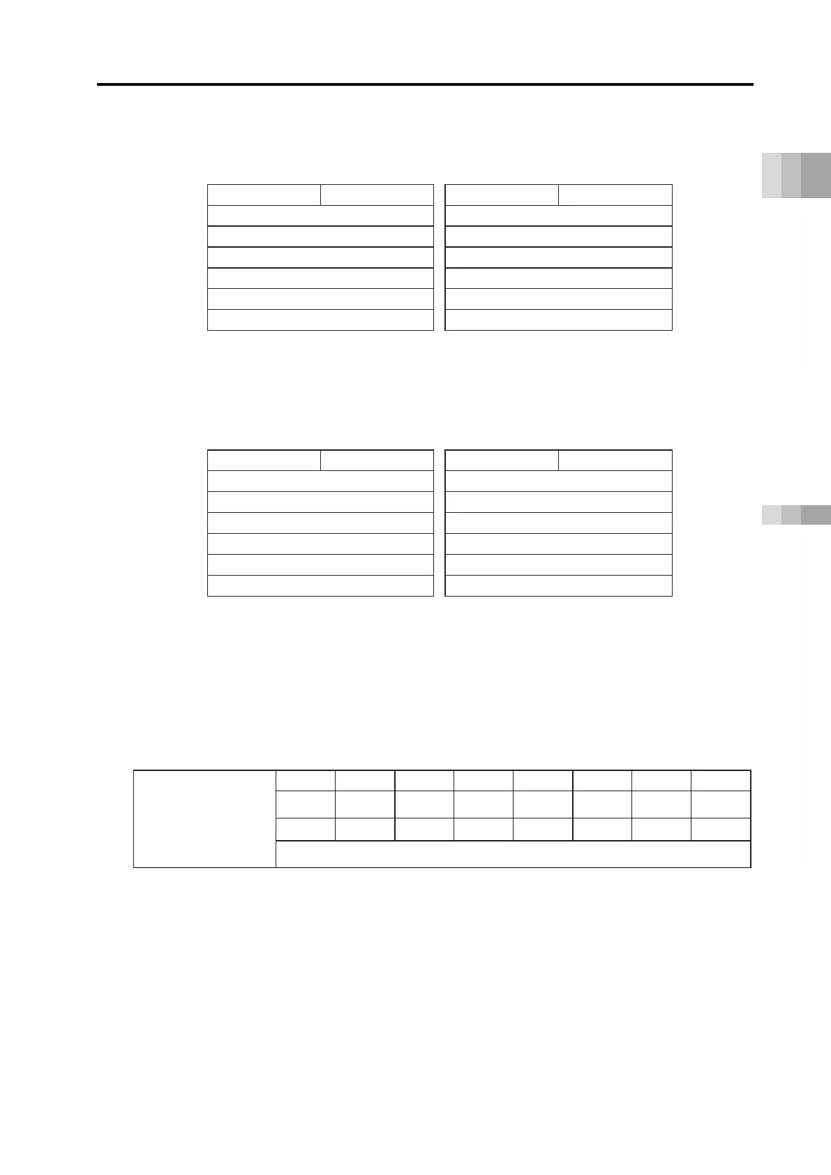
(3) For PROFIBUS-DP, EtherNet/IP, and EtherCAT
*1
PLC output
⇒
gateway
⇒
each axis input
Each axis output
⇒
gateway
⇒
PLC input
Power supply unit status signal 0
Power supply unit status signal 1
Power supply unit status signal 2
Power supply unit status signal 3
Power supply unit status signal 4
*1 b8 to b15 of the high byte are b0 to b7.
(4) For PROFINET-IO
PLC output
⇒
gateway
⇒
each axis input
Each axis output
⇒
gateway
⇒
PLC input
Address b15 High byte b8
b7 Low byte b0
b15 High byte b8
b7 Low byte b0
+0
Not available Power supply unit status signal 0
Not available Power supply unit status signal 1
+1
Power supply unit status signal 2
Power supply unit status signal 3
Power supply unit status signal 4
*2 PROFINET-IO uses 4-word unit module addresses.
(2) I/O signal
The details of the power supply unit status signal address configuration are as follows.
PLC
input
Power supply unit
Status signal 0~4
LNK - - - - OPMV FANW FANA
PSMV