3.8 I/O Signals
A3-115
ME0384-4A
[2] Alarm clear input (RES) PLC output signal
● When the [RES] signal is turned ON, the currently triggered alarm will be cleared.
● Alarm clear may not be possible depending on the alarm itself.
Refer to "Maintenance Section Chapter 2, 2.5 Troubleshooting for ELECYLINDER alarm
groups (Page C2-30)" for detail.
[3] Position detection output backward end/forward end (LS0/LS1) PLC input signal
● The LS signals perform the same operation as an air cylinder automatic switch.
They are not positioning complete signals.
● The LS signals turn ON when the current ELECYLINDER position is within the detection
range configured at the backward and forward ends.
● They turn ON when within the detection range regardless of whether the servo is ON or
OF F.
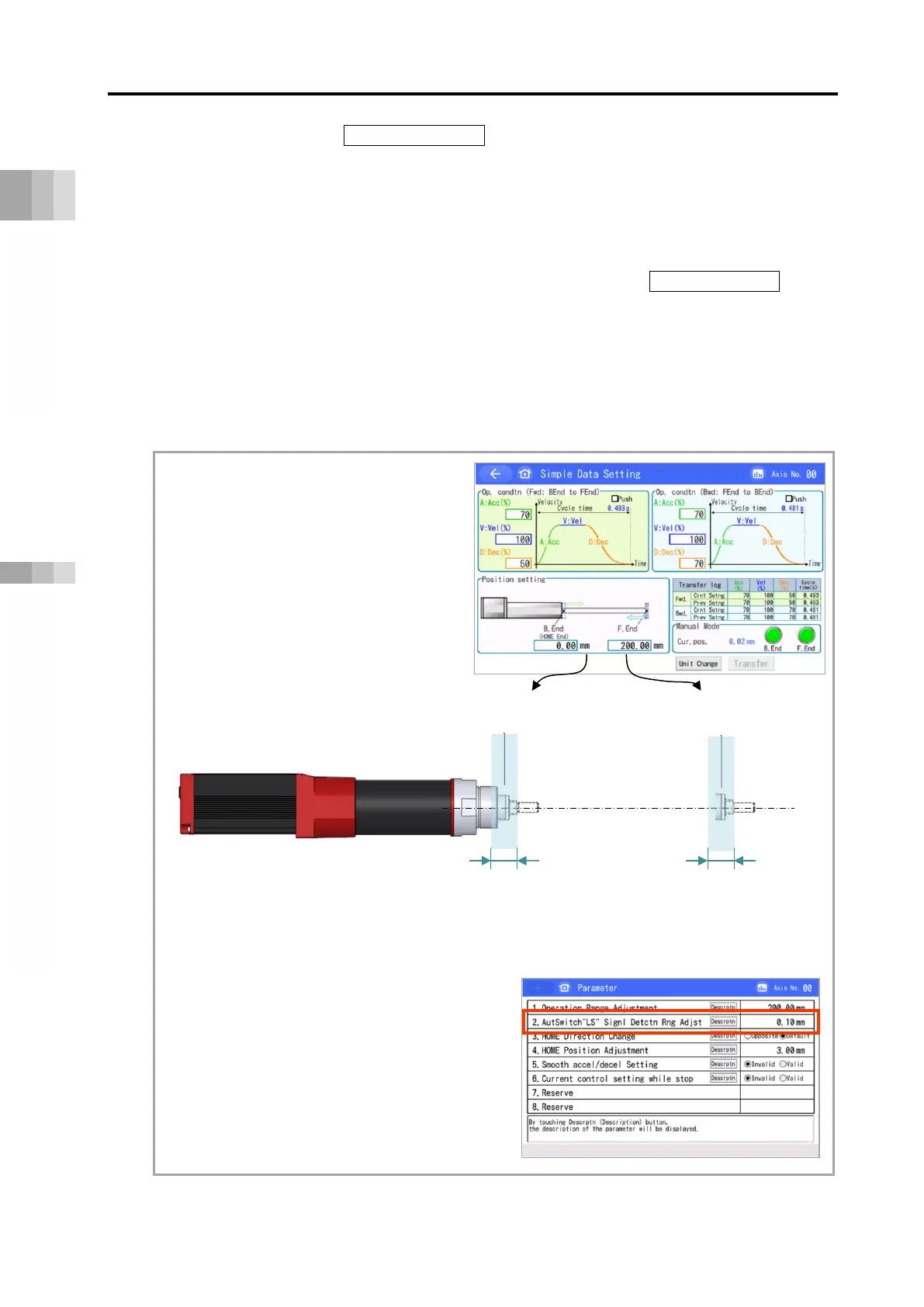
The backward end and forward end
set values' relationship to [LS0]
and [LS1] signals ON is as follows.
In this example, the LS signal
detection range is ±0.10mm.
To adjust the LS signal detection range,
open the [Edit parameters window].
Parameter No.2
[Auto switch LS signal detection range
adjustment] can be used to
make adjustments.
Backward end
Forward end
[LS0 detection range]
[LS1 detection range]

 Loading...


