3.8 I/O Signals
A3-144
ME0384-4A
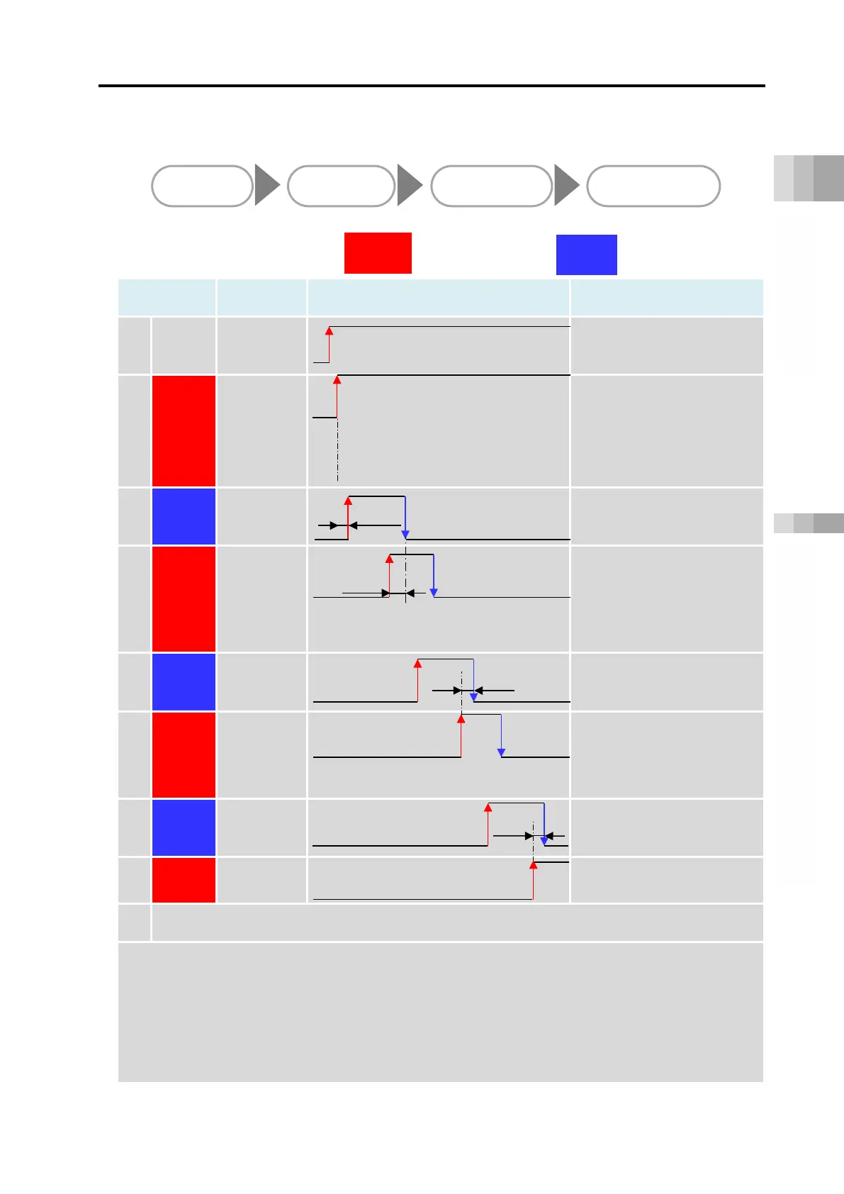
This shows the PLC timing chart for operating the ELECYLINDER.
The basic process is as follows.
[Basic timing chart]
Category
Timing chart Remarks
1 Power Power ON
EC Connection Unit
SYS LED
On
24VDC power supply is
turned ON.
2 Output
*ALM
E*RD
*ALM:Turns ON if no alarm
has been triggered.
E*RD: It turns on when
operation ready
(servo on)
3 Input
ST0
∆t1
turned ON, home return
4 Output
LS0
∆t2
EC Connection Unit
Backward End LED: On
Home return operation is
complete and the unit
moves to the backward end.
5 Input
ST1
∆t2
Moves to the forward end.
6 Output
LS1
EC Connection Unit
Moved to the forward end.
7 Input
ST0
∆t2
Moves to the backward end.
8 Output
LS0
Moved to the backward end.
9
After this, "5" to "8" repeat.
∆t1: Wait approximately 0.5 seconds from when the E*RD signal turns ON before inputting the
first command.
t2: The time taken for the ELECYLINDER actually to reach the forward or backward end after
the LS signal turns ON. Consider
t2 when giving instructions for the next operation from
the PLC to the ELECYLINDER.
Also,
t2 varies depending on the communication time among PLC ⇔ EC connection unit
⇔
ELECYLINDER, size of payload and acceleration/deceleration.
Output
Input
ELECYLINDER
output signals to PLC
PLC
input signals to
ELECYLINDER

 Loading...


