2.2. Wiring
B2-16
ME0384-4A
Chapter 2 Mounting and Wiring
[CC-Link dedicated cable and cable connector wiring method]
Point!
●
The terminal resistor to be used may differ depending on the CC-Link dedicated cable type.
Cable FANC-SBH (CC-Link dedicated high-performance cable): Terminal resistor: 130 Ω
Cable FANC-SB (CC-Link dedicated cable): Terminal resistor: 110 Ω
-Link dedicated cable.
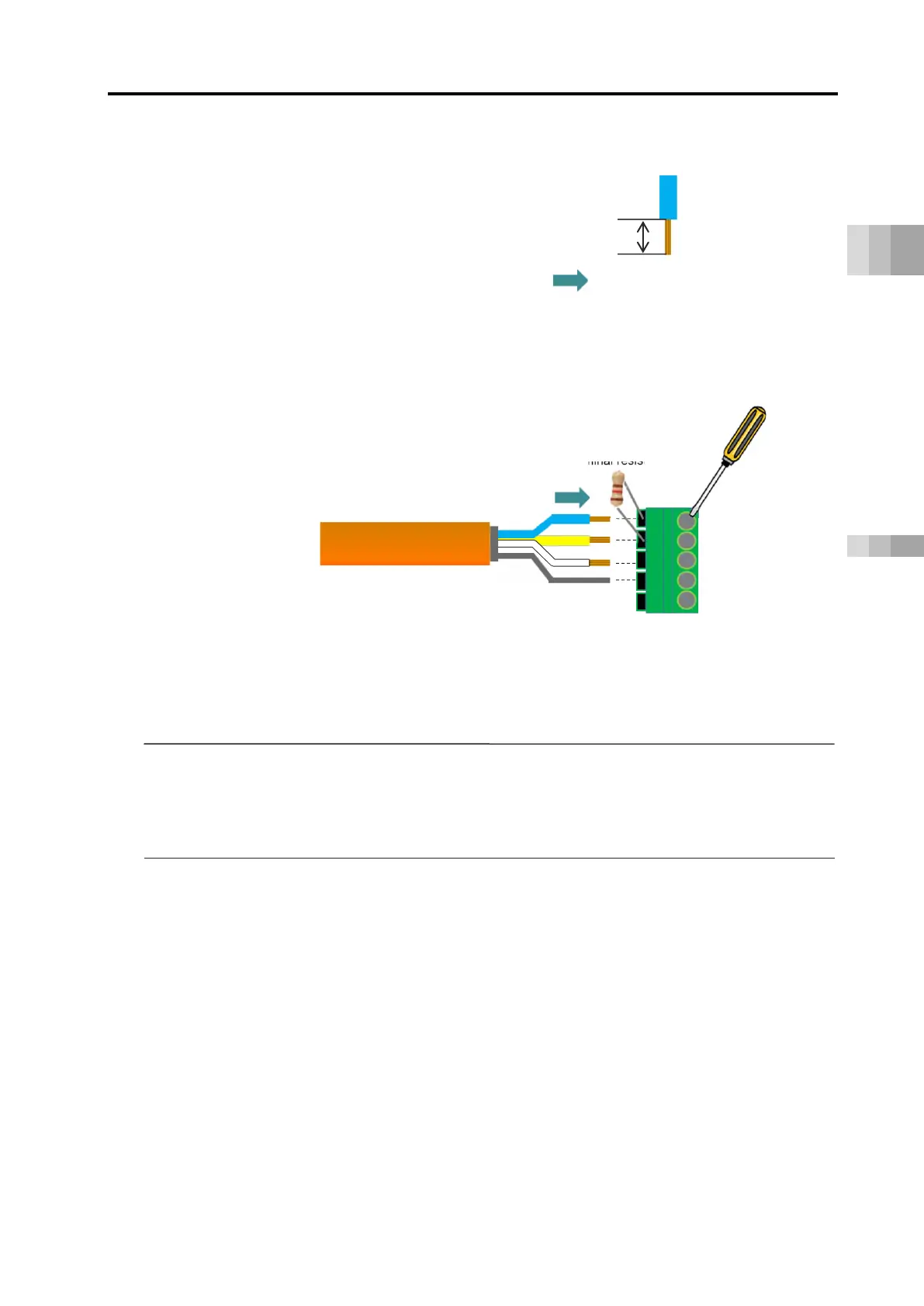
(2) Strip 7mm of insulation from each wire end.
(3) Insert the stripped wiring in the direction of the
arrow
in the figure below to the back
of the connector and tighten with a flathead screwdriver.
in "Connection image" above)
Attach the controller attached terminal resistor (Note 1) between the connectors DA and
DB at the network terminal end only.
7mm
* The terminal resistor of the CC-Link master unit is
to be prepared by the customer.
-
Link dedicated cables are wired in the same manner as in (1) to (4).
CC-Link
dedicated cable
CC-Link cable connector
(MSTB2.5/5-STF-5.08AU)
 Loading...


