2.2. Wiring
B2-18
ME0384-4A
Chapter 2 Mounting and Wiring
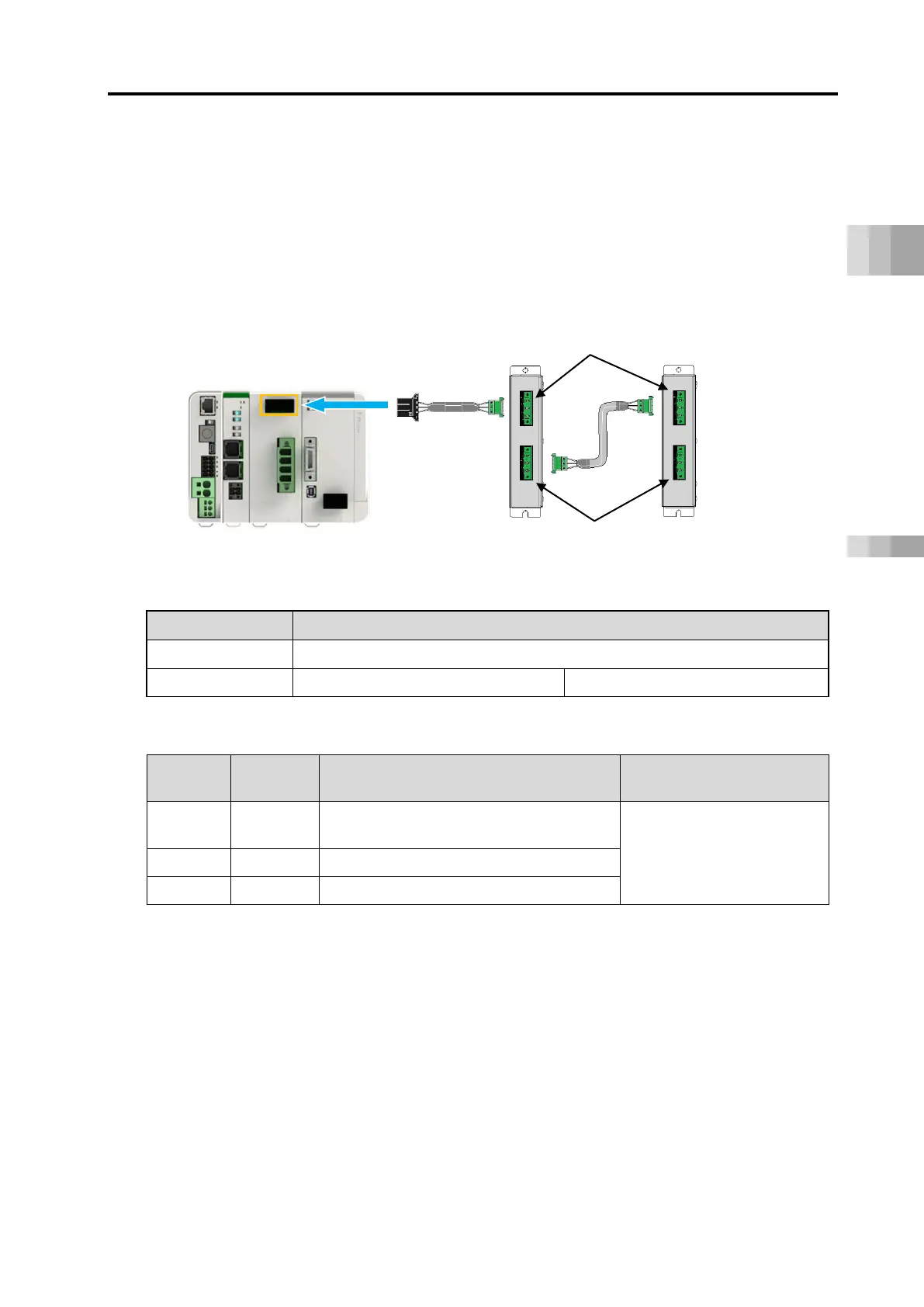
[Wiring for Regenerative Resistor Unit]
Connect the regenerative resistor units as shown in the figure below with using the cables
enclosed to the regenerative resistor units.
(1) Connecting 1 Unit: Connect RESU(D)-2 with enclosed cable (CB-SC-REU)
(2) Connecting 2 or More: Connect RESU(D)-1 with enclosed cable (CB-ST-REU)
● Wiring Image
● External Regenerative Resistor Connector Specifications
External Regenerative Resistor Connector (RB)
Controller side: 1-178138-5
● Pin Assignment
Pin No.
Items
Applicable cable
diameter
1 RB+
Regeneration Resistor +
(Motor drive DC voltage)
Dedicated Cable Enclosed
to Regenerative Resistor
Unit
External Regenerative Resistor Connector
RESU-2
RESUD-2
RESU-1
RESUD-1

 Loading...


