4.4 Address Configuration
B4-47
ME0384-4A
Chapter 4 Network Configuration
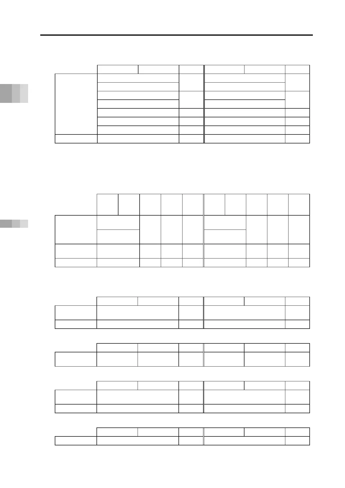
(2) Direct numerical control mode data region configuration
PLC output
each axis input Each axis output
PLC input
Direct
specified
region
Specified position data (L)
*
2
Present position data (L))
*
2
Specified position data (H))
*
Present position data (H))
*
Specified positioning width (L))
*
2
Present current value (L))
*
2
Specified positioning width (H))
*
Present current value (H))
*
Specified acceleration/deceleration
Pushing current limit value
*(L) is the low word of a 2-word datum while (H) is the high word of a 2-word datum.
Note 1: The present current value should be the command current value for the stepper motor
and be the feedback current value for the AC servomotor (including AC servomotor
connected to SCON-CB).
(3) Simple direct mode and positioner 1 mode data region configuration
PLC output ⇒ each axis input
Each axis output ⇒ PLC input
High
byte
Low
byte
Word
count
direct
1 mode
High
byte
Low
byte
Word
count
direct
1 mode
Position data
specified
region
Specified
position data (L)
2 ○ x
*
Present position
data (L)
2 ○ ○
Specified
position data (H)
Present position
data (H)
Position
specified region
1 ○ ○
1 ○ ○
* Positioner 1 mode does not use the position data specified region (PLC ⇒ each axis input), but
it is occupied as a data region.
(4) Positioner 2 mode data region configuration
Position
specified region
Command position No. 1 Completed position No. 1
(5) Positioner 3 mode data region configuration
High byte Low byte
Word count
High byte Low byte
Word count
Control signal region
Control signal
1 Status signal
1
(6) Positioner 5 mode data region configuration
Position
specified region
Command position No. 1
Present position data
(0.1 mm increments)
1
(7) Data Domain Construction of EC Connector Unit
Control signal (for four axes)
Control signal (for four axes)

 Loading...


