EasyManuals Logo

ICON A5 User Manual

ICON A5
836 pages
To Next Page IconTo Next Page
To Previous Page IconTo Previous Page
Page #162 background imageLoading...
Page #162 background image
6-34 ELECTRICAL SYSTEM / ELECTRICAL SYSTEM GENERAL MAINTENANCE
ICON A5 / MAINTENANCE MANUAL CHANGE C2
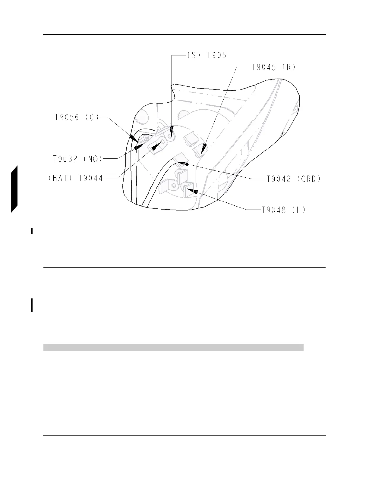
CHAPTER 6
FIGURE 6-1
BACK VIEW OF THE IGNITION SWITCH
7. Remove the cap from the new ignition switch and install the ignition switch to the left hand cross-
beam.
8. Screw the new cap onto the ignition switch to secure it to the left hand crossbeam.
VERIFICATION METHOD:
The task is complete when the switch is secured to the left hand crossbeam and verified to function
correctly by turning on the aircraft.
6.4.2 Inspect, Repair, and Secure Wiring Harness with Signs of Chafing
Use the following procedure to inspect the wiring harness for chafing, security, and condition.
TASK INFORMATION:
Type of Maintenance
Line
Level of Certification
LSA-RM
Task Specific Training Required

Table of Contents

Other manuals for ICON A5

Questions and Answers:

Question and Answer IconNeed help?

Do you have a question about the ICON A5 and is the answer not in the manual?

ICON A5 Specifications

General IconGeneral
ManufacturerICON Aircraft
EngineRotax 912 iS
Horsepower100 hp
Wingspan34.8 ft (10.6 m)
Length23 ft (7.0 m)
Height8.1 ft (2.5 m)
Maximum Takeoff Weight1, 510 lb (685 kg)
Seating Capacity2
TypeLight Sport Aircraft
Propeller3-blade composite
Fuel Capacity20 gallons
Maximum Speed109 knots
Cruise Speed95 knots
Stall Speed45 mph (72 km/h, 39 knots)
Range427 nmi (491 mi, 790 km)
Rate of Climb1, 000 ft/min
Service Ceiling15, 000 ft