FLIGHT CONTROLS / FLAP CONTROLS 9-71
CHANGE C3 ICON A5 / MAINTENANCE MANUAL
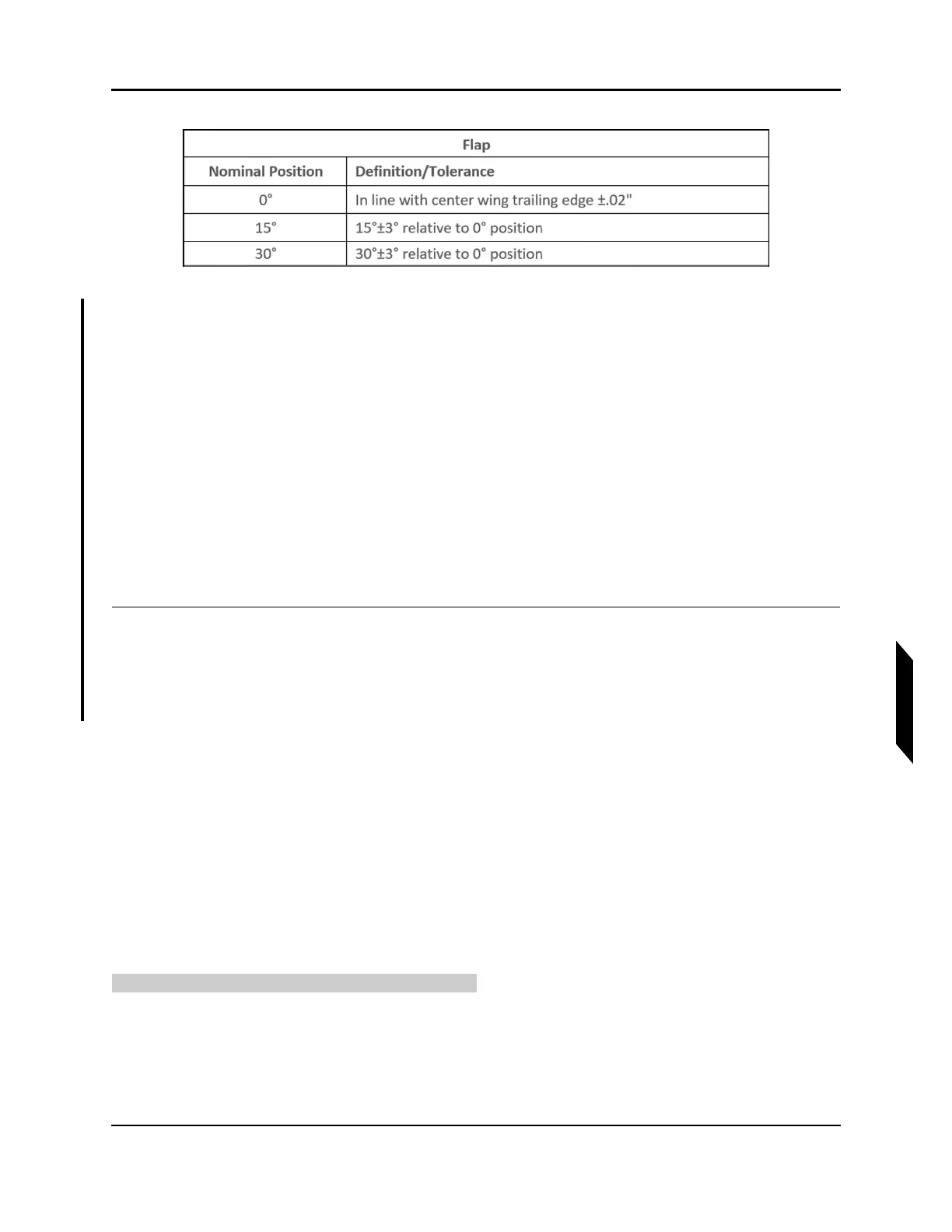
FIGURE 9-45
FLAP POSITION LIMIT
a. Actuate the flap by hand. If the pushtube contacts the flap or wings, it is permissible to bias
the pushtube body forward as necessary to eliminate the interference.
b. The outboard flap pin will move inboard or outboard by adjusting rod end C. Set the rod end
length such that the outboard flap pin contacts the fuselage flap pin. Ensure the flap bell-
crank still contacts the up-stop after setting rod end C length. Actuate the flaps and set the
15° and 30° actuator stops to limit the flap range of motion as described in Figure 9-45
above.
c. See Figure 9-43 for actuator stop locations. Actuate the flaps to 30° then back to 0°. Verify
the flap returns to 0° due to the gas spring extension force. If the system does not return,
adjust the 30° actuator stop to reduce range of motion. Ensure the flap travel limits are still
within the tolerance specified in Figure 9-45.
6. Install AFT baggage panel. (See “Removal and Installation of Inspection Panels and Fairings” on
page 3-34.)
VERIFICATION METHOD:
Conduct the Check Flap Rigging Procedure (See “Inspect Flap Rigging” on page 9-65.) to verify proper
rigging.
RELATED INFORMATION:
"Removal and Installation of Inspection Panels and Fairings" on page 3-34
"Inspect Flap Rigging" on page 9-65
"Install Flap Actuator" on page 9-74
9.9.4 Maintenance Instructions
9.9.4.1 Remove Flap Actuator
Use these instructions to remove the flap actuator.
TASK INFORMATION:
Type of Maintenance
Line