9-70 FLIGHT CONTROLS / FLAP CONTROLS
ICON A5 / MAINTENANCE MANUAL CHANGE C3
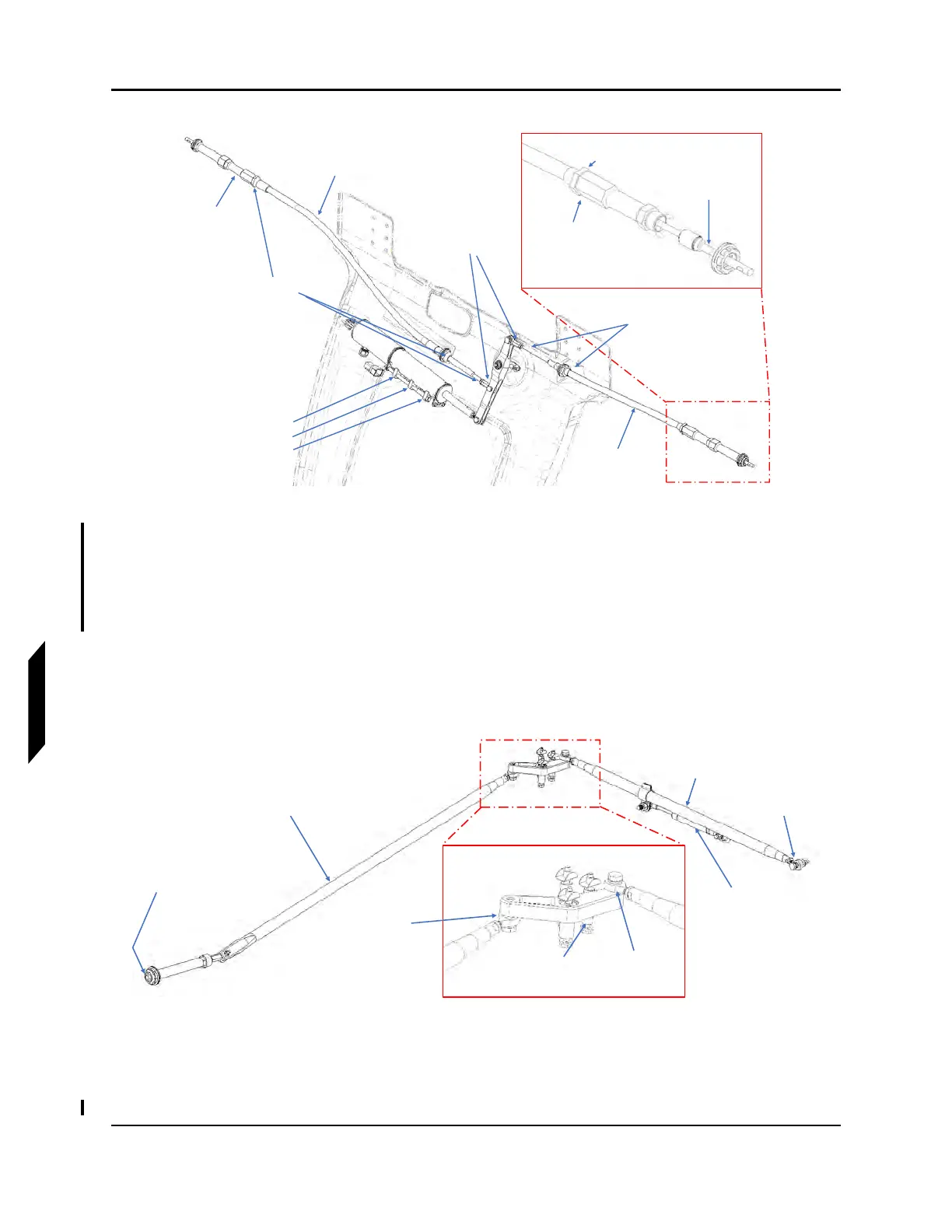
FIGURE 9-43
FLAP RIGGING DIAGRAM
4. If not extended, extend and lock wings.
5. Adjust the outboard push tube. Adjust rod end A and B length equally such that the flap bellcrank
contacts the up-stop and the flap trailing edge lines up with the trailing edge of the center wing
as described in Figure 9-44. Refer to Figure 9-43 for actuator location.
FIGURE 9-44
WING FLAP SYSTEM OVERVIEW
Push Cable
Push Cable
Jam Nuts
Jam Nuts
Bellcrank
Rod Ends
Interconnect
Actuator Stops:
30°
15°
0°
Fuselage
Flap Pin
Cable
Socket
Jam Nut
Inboard
Pushtube
Outboard
Pushtube
Rod End C
Gas Spring
Rod End A
Rod End B
Up Stop
Outboard
Flap Pin