FLIGHT CONTROLS / FLAP CONTROLS 9-65
CHANGE C3 ICON A5 / MAINTENANCE MANUAL
9.9 Flap Controls
9.9.1 Flap Controls Description
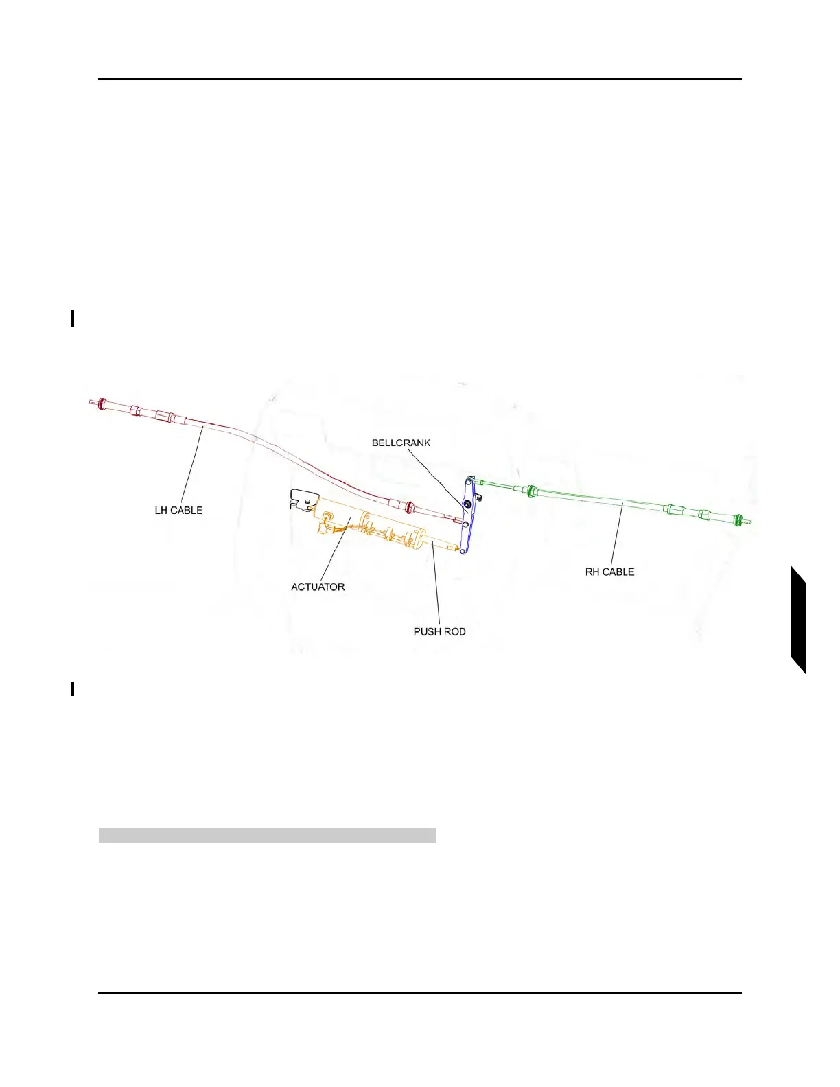
The flap control surfaces are driven by an electric actuator. There are three positions for the flaps: 0°,
15°, and 30°. When the pilot turns the knob to move the flaps, the linear actuator moves a system of
pushrods and bellcranks, which in turn moves the wing flaps down. The flaps return to the zero position
using gas struts.
9.9.2 Flap Controls Diagram/Schematic
FIGURE 9-42
FLAP CONTROLS OVERVIEW
9.9.3 Inspection Instructions
9.9.3.1 Inspect Flap Rigging
Perform ground rigging inspection check on A5 flaps.
TASK INFORMATION:
Type of Maintenance
Line
Level of Certification