FLIGHT CONTROLS / YAW CONTROLS 9-79
CHANGE C3 ICON A5 / MAINTENANCE MANUAL
9.10 Yaw Controls
9.10.1 Yaw Controls Description
The rudder is controlled by the Yaw Control System. When the pilot moves the rudder pedal, the yaw
cable connected through FWD and AFT bellcranks will move the rudder accordingly.
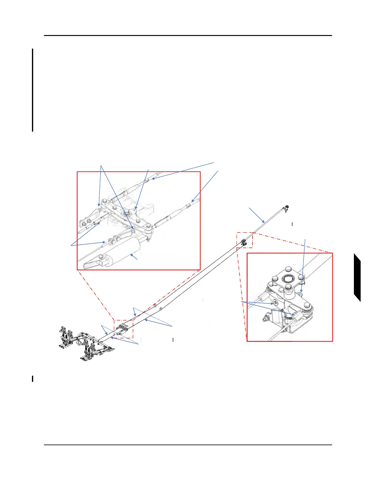
9.10.2 Yaw Controls Diagram/Schematic
FIGURE 9-50
YAW CONTROLS OVERVIEW
FWD Yaw
Turnbuckles
FWD Yaw Bellcrank
Rig Pin Location
AFT Yaw Bellcrank
Rig Pin Location
Rudder Push
Tube
Primary Stops
Secondary Stops
Fwd Yaw Cable
Tensiometer Location
Rudder Return
Spring
FWD Yaw
Turnbuckles
AFT Yaw Cable
Tensiometer Location
w
R
T
Pr
mar
Sto
s
T
n
i
m
t
r L
ti
R
r R
t
r
S
rin
FT Y
w C
T
n
i
m
t
r L
ti