ELECTRICAL SYSTEM / BILGE PUMP 6-47
CHANGE C2 ICON A5 / MAINTENANCE MANUAL
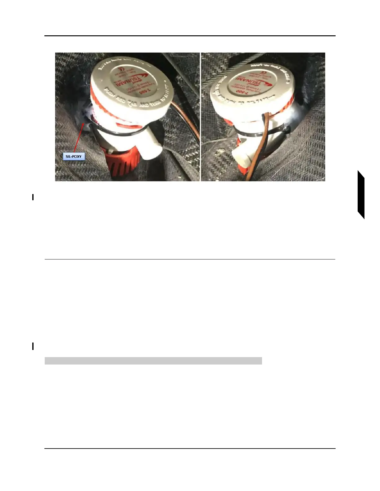
FIGURE 6-9
APPLY SIL-POXY
7. Attach the bilge pump hose to the pump barb fitting and secure with a 20-32/9-WS hose clamp.
8. Connect D9009J connector on bilge pump to D9009P connector on main wire harness.
9. Test that the bilge pump operates normally.
10. Install the fuel tank mounting structure if needed.
11. Install the fuel tank. (See “Install Fuel Bladder (MY17 Only)” on page 10-12.)
VERIFICATION METHOD:
The task is complete when both the bilge pump and the fuel bladder tank are installed.
RELATED INFORMATION:
"Install Fuel Bladder (MY17 Only)" on page 10-12
6.6.3.4 Bilge Pump Removal (MY18+)
The following procedure should be used to remove the bilge pump (MY18+).
TASK INFORMATION:
Type of Maintenance
Line
Level of Certification
LSA-RM
Task Specific Training Required