6-54 ELECTRICAL SYSTEM / WING TIP LIGHTS
ICON A5 / MAINTENANCE MANUAL CHANGE C2
Special Tools Required
None
Parts Required
None
Aircraft System and Number
03—Electrical System
Consumables
None
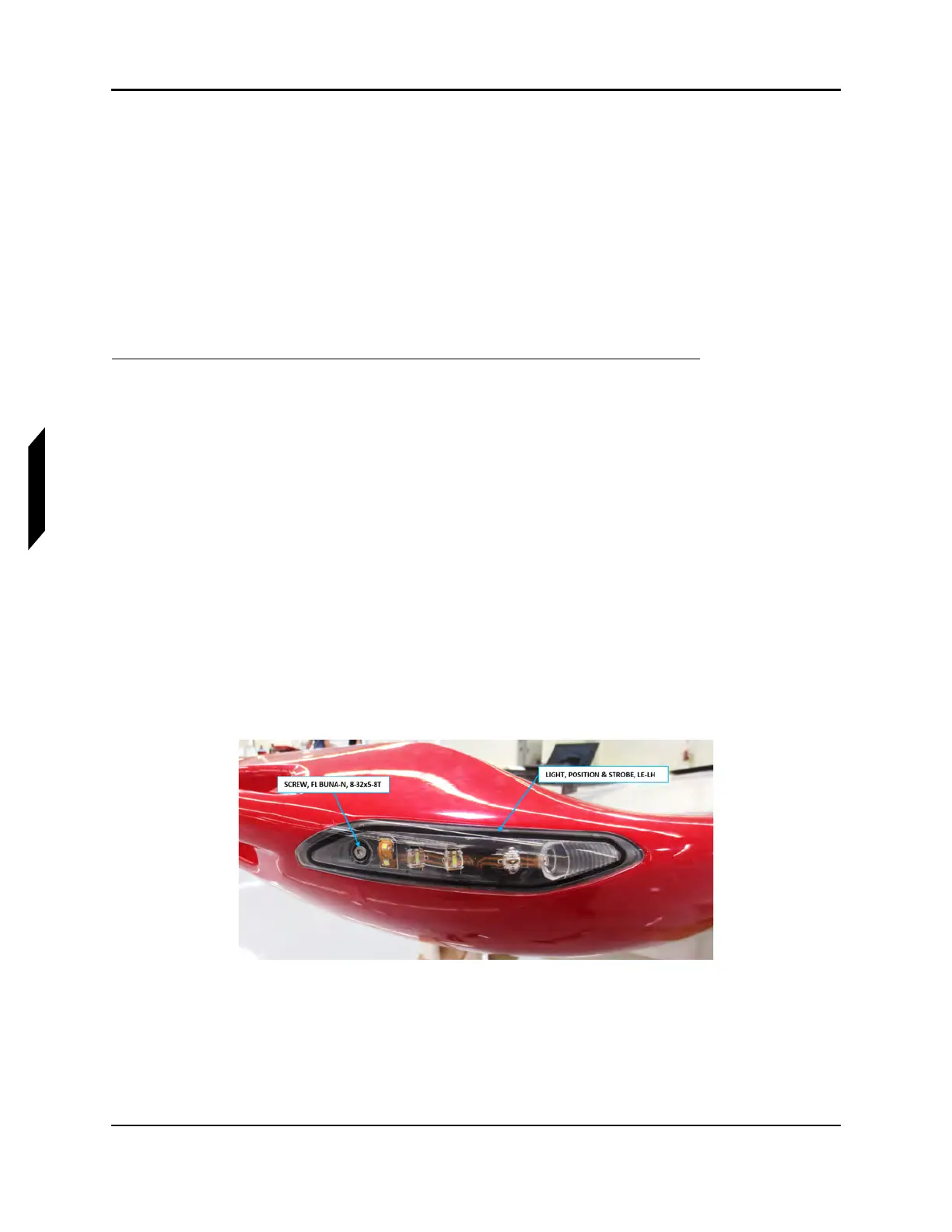
1. Using a T15 Torx screwdriver, remove the retention screw on each leading edge and tail edge
light as needed.
NOTE: If the retention screw is not being replaced , ensure the O-ring
remains on it.
2. Detach light from aircraft and disconnect the light’s wire harness connectors.
a. Disconnect D90002J1 and D9002P2 on LIGHT, POSITION & STROBE, LE-LH from
D9002P1 and D90002J2 on aircraft wire harness, respectively.
NOTE:
b. Disconnect D9003P on LIGHT, POSTION & STROBE, TE-LH from D9003J on aircraft wire
harness.
c. Disconnect D9006J1 and D9006P2 on LIGHT, POSITION & STROBE, LE-RH from
D9006P1 and D9006J2 on aircraft wire harness, respectively.
d. Disconnect D9007P on LIGHT, POSITION & STROBE, TE-RH from D9007J on aircraft
wire harness.
FIGURE 6-13
LEADING EDGE LIGHT ASSEMBLY, LH