9-86 FLIGHT CONTROLS / YAW CONTROLS
ICON A5 / MAINTENANCE MANUAL CHANGE C3
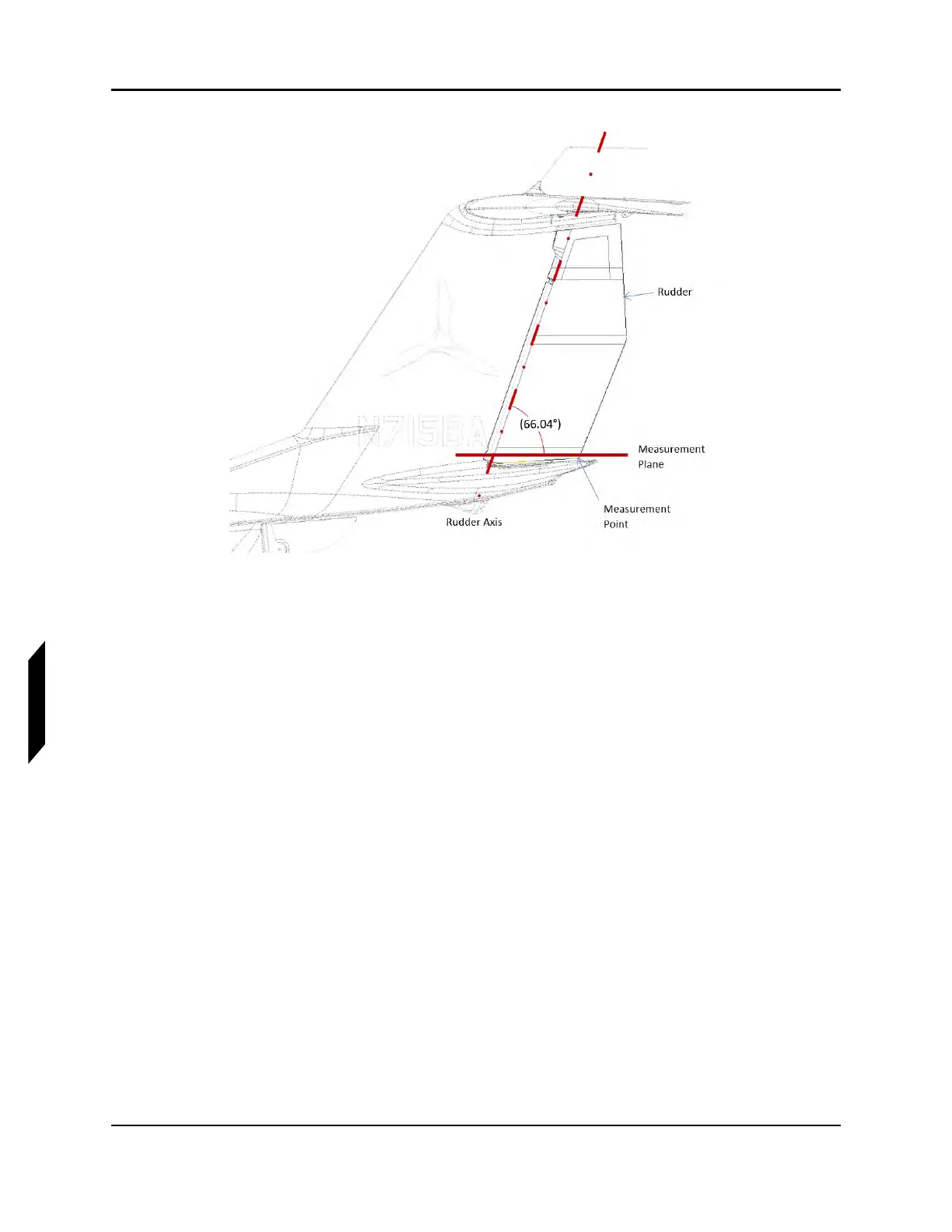
FIGURE 9-53
RUDDER MEASUREMENT PLANE
3. With the aid of another person, check the rudder maximum travel limits. Have a helper push each
rudder pedal against the stop (stop contacts at water rudder bellcrank should be heard). While
holding very light (1-2 lbf) pressure towards neutral on the rudder trailing edge to remove play.
4. Maximum travel limits are set as specified. See Figure 9-54.
a. Trailing Edge Left: 11°+/-1°
b. Trailing Edge Right: 14°+/-1°