LANDING GEAR / TROUBLESHOOTING 14-9
CHANGE C2 ICON A5 / MAINTENANCE MANUAL
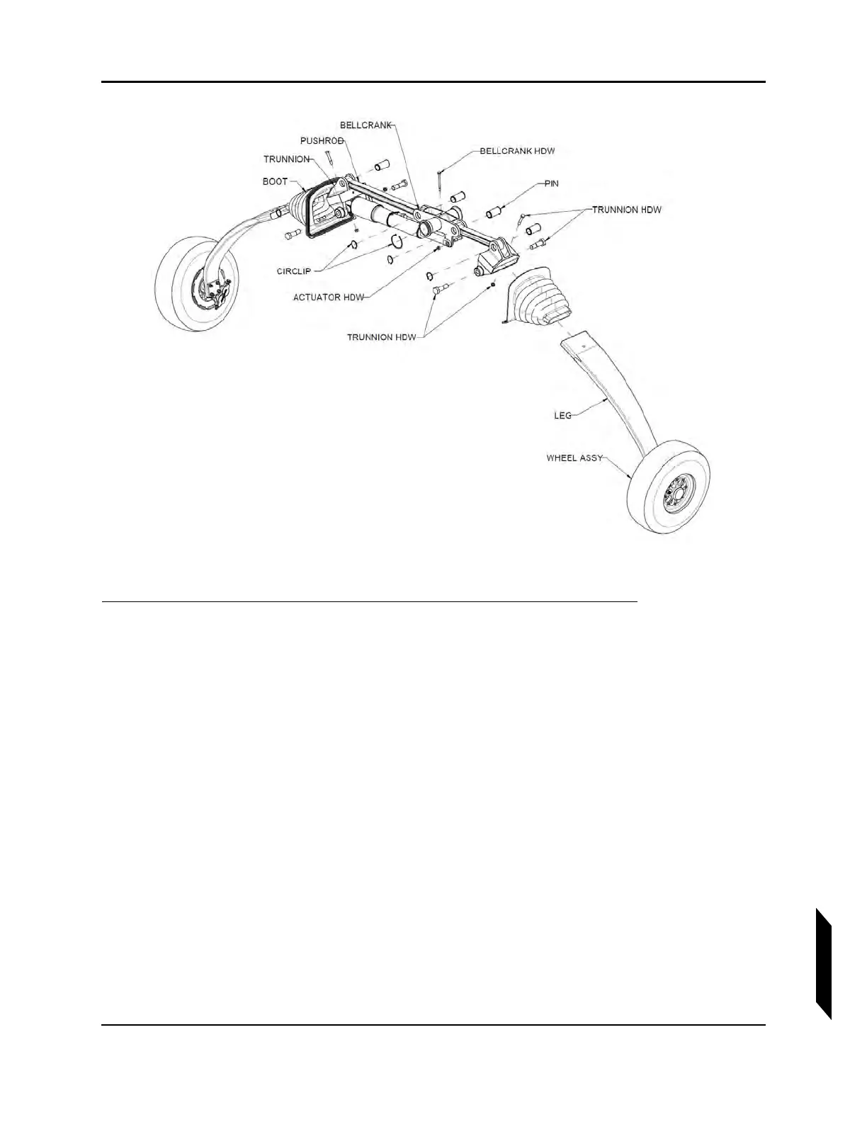
FIGURE 14-2
MAIN LANDING GEAR ASSEMBLY DETAIL.
1. Remove the Aft Bulkhead Baggage Panel. (See “Removal and Installation of Inspection Panels
and Fairings” on page 3-34.)
2. Jack the aircraft using the built-in jack points. (See “Empty Weight and CG Measurement While
on Jackpoint Scales” on page 3-32.)
3. Check for mechanical attachment.
a. Vibrate the entire main landing gear by grabbing the gear from the exterior and applying an
alternating force.
b. From the interior of the aircraft, again, vibrate the control system by rotating the bell crank
clockwise and counter-clockwise. There should not be an excessive amount of play or
travel in the system.
4. Ensure the mechanical fasteners has not been broken or tampered with.
5. Confirm that all circlips are still correctly installed, refer to illustration.
6. Verify that attachment hardware for the landing gear trunnions is correctly installed, refer to the
illustration for the location of trunnion attachment hardware.
7. Inspect both legs of the main landing gear for any hairline fractures.
8. Inspect both main landing gear boots for wear or tears. Check the bonded joints between boot
and leg and between boot and Seawings™. Use care to thoroughly inspect along the entire