PROPULSION / ENGINE 16-53
CHANGE C2 ICON A5 / MAINTENANCE MANUAL
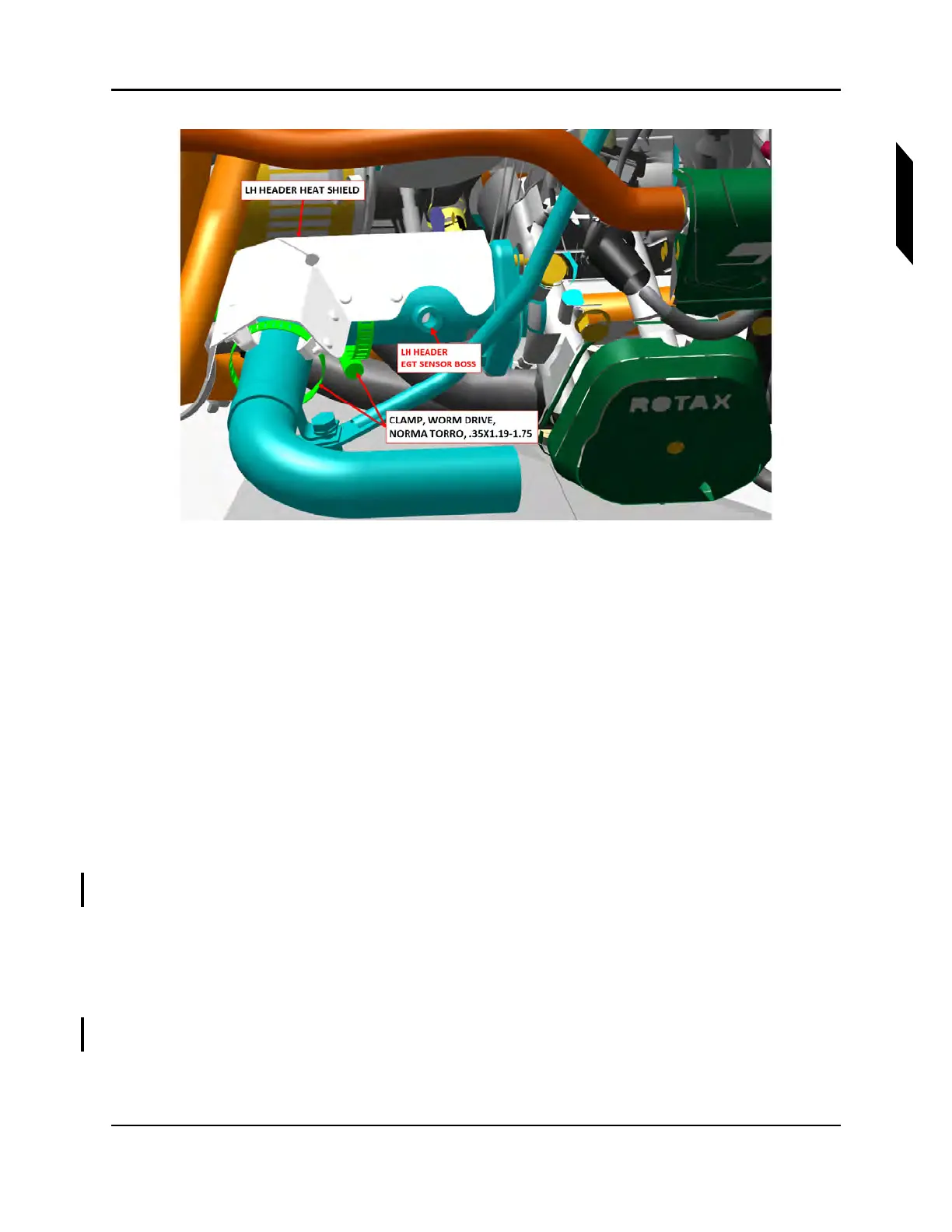
FIGURE 16-33
HEADER HEAT SHIELD INSTALLATION
12. Clean and apply LUBRICANT, ANTI-SEIZE to threads of EGT sensor nut.
13. Attach EGT sensor to FWD header boss and torque to 19 ft-lb (228 in-lb) with a 17 mm wrench.
14. Install muffler shield (inner cowl), and secure with #15 Torx countersunk screw below FWD
header. Apply LUBRICANT, GENERAL PURPOSE and torque screws to 26 in-lb.
15. If the mufflers are not already assembled to the aft headers as a sub-assembly, perform the
following steps:
a. Clean the slip joint interfaces of muffler and aft header.
b. Apply a thin coat of LUBRICANT, ANTI-SEIZE to the slip joint interfaces.
c. Install AFT headers into the associated muffler. The anti-rotation tabs should overlap so
that the tab on the muffler lies outboard of the tab on the header.
NOTE: The mufflers and headers are not left/right interchangeable.
d. Secure aft header to muffler using MS20995C41 safety wire.
e. Wrap safety wire through the overlapping hole and over the top of the tabs three times,
pulling it tight.
f. Then, wrap the wire through the overlapping hole and then through the aft hole in the
header tab three times, pulling it tight.
g. Twist the ends of the wire together per standard practice and bend free end over to avoid
a poke hazard.
16. Clean pipe and apply a thin coat of LUBRICANT, ANTI-SEIZE to the last 2 inches of FWD and
AFT headers.
17. Install the muffler sub-assembly by sliding it forward onto the FWD header and onto the engine
exhaust port studs.