MAINTENANCE AN D SERVICING
5. Insert spindle (A) into cutterbar.
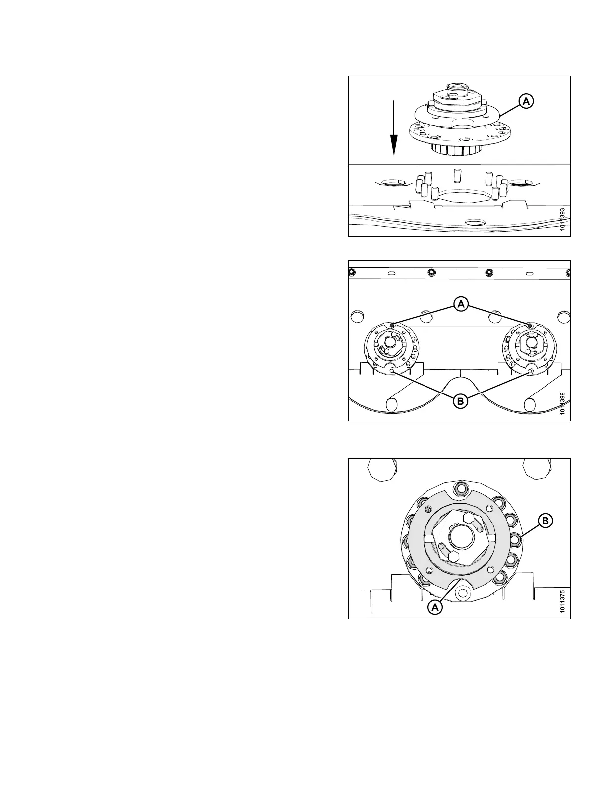
Figure 4.41: Left-Hand Spindle
6. Insert studs (A) into spindle as shown.
NOTE:
Plugsarefactoryinstalledasshowninposition
(B) but may come loose over time. Ensure studs
are inserted into proper location.
IMPORTAN T:
Ensure c
lockwise spindles rotate clockwise
and coun
terclockwise spindles (with machined
grooves
) rotate counterclockwise. The offset
gear des
ign mak es it possible to install spindles
having a
n opposite rotation of what is intended
which w
ill prevent discs from spinning up after
impact
resulting in cutterbar component damage.
Figure 4.42: Spindle Orientation
7. Rotate spindle hub (A) to access studs, and install
eleven M12 lock nuts (B) and washers.
Figure 4.43: Left-Hand Spindle Hub
and Hardw are
147910 139 Revision A