MAINTENANCE AND SERVICING
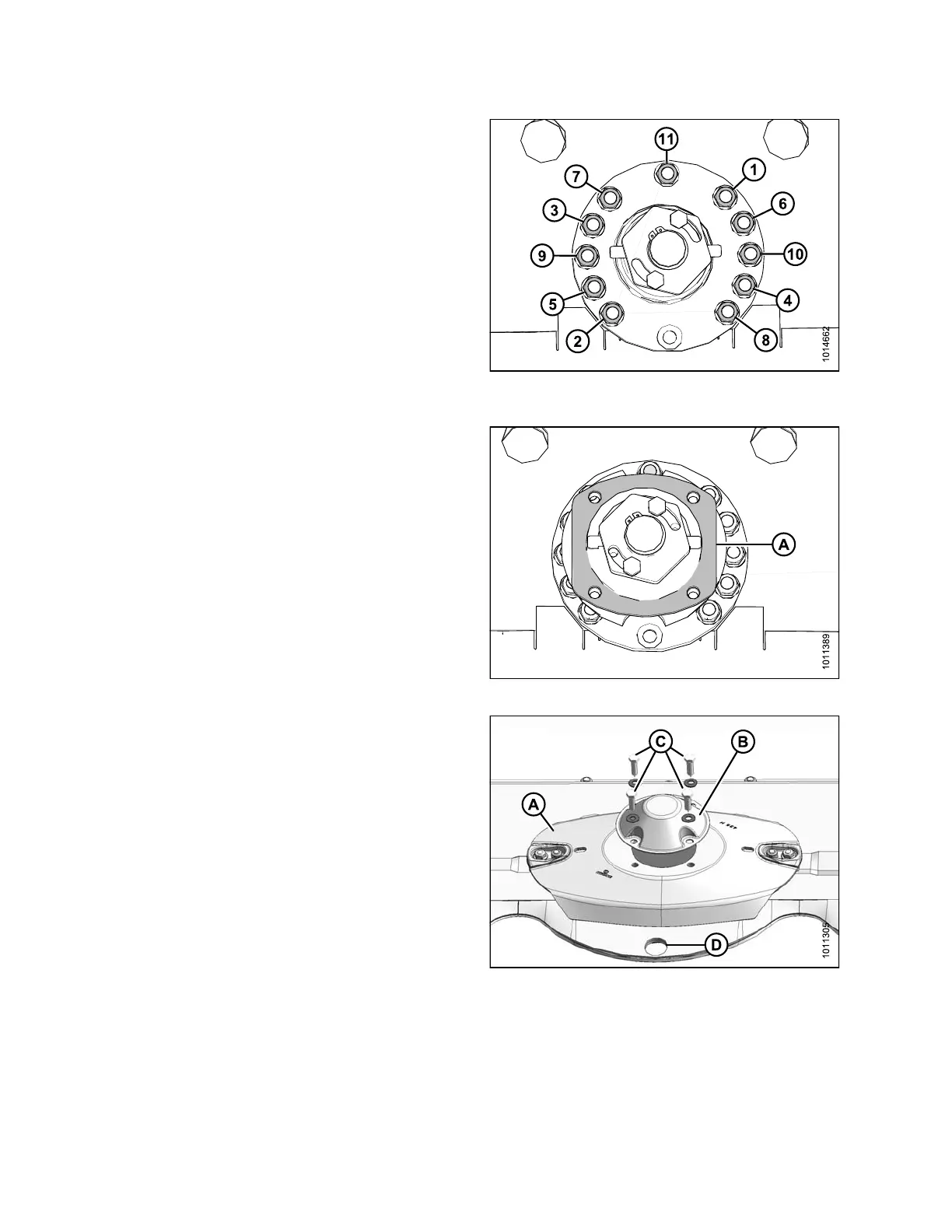
8. Torque bolts to 37 ft·lbf (50 N·m) following the
tightening pattern shown at right.
Figure 4.44: Tightening Pattern (Hub Removed
for Clarity)
9. Install spacer plate (A).
Figure 4.45: Spacer Plate
10. Place a pin (or equivalent) in the front hole of the rock
guard (D) to prevent disc rotation while tightening bolts.
IMPORTANT:
Blades are rotation specific. It is necessary to
switch entire disc w hen swapping sp indles.
11. Pos ition disc (A) on spindle ensuring that it
is positioned at a 90° angle in relation to the
adjacent discs.
NOTE:
Turn disc (A) by hand to ensure cutterblades do
not contact each other or adjacent discs.
12. Install cutte r disc cap (B ) and secure assem bly with
four M12 bolts and washers (C). Torque bolts to 63 ft ·lbf
(85 N·m).
Figure 4.46: Cutterbar Disc and Cap
147910 140 Revision A