MAINTENANCE AND SERVICING
6. Remove sp ac er (A).
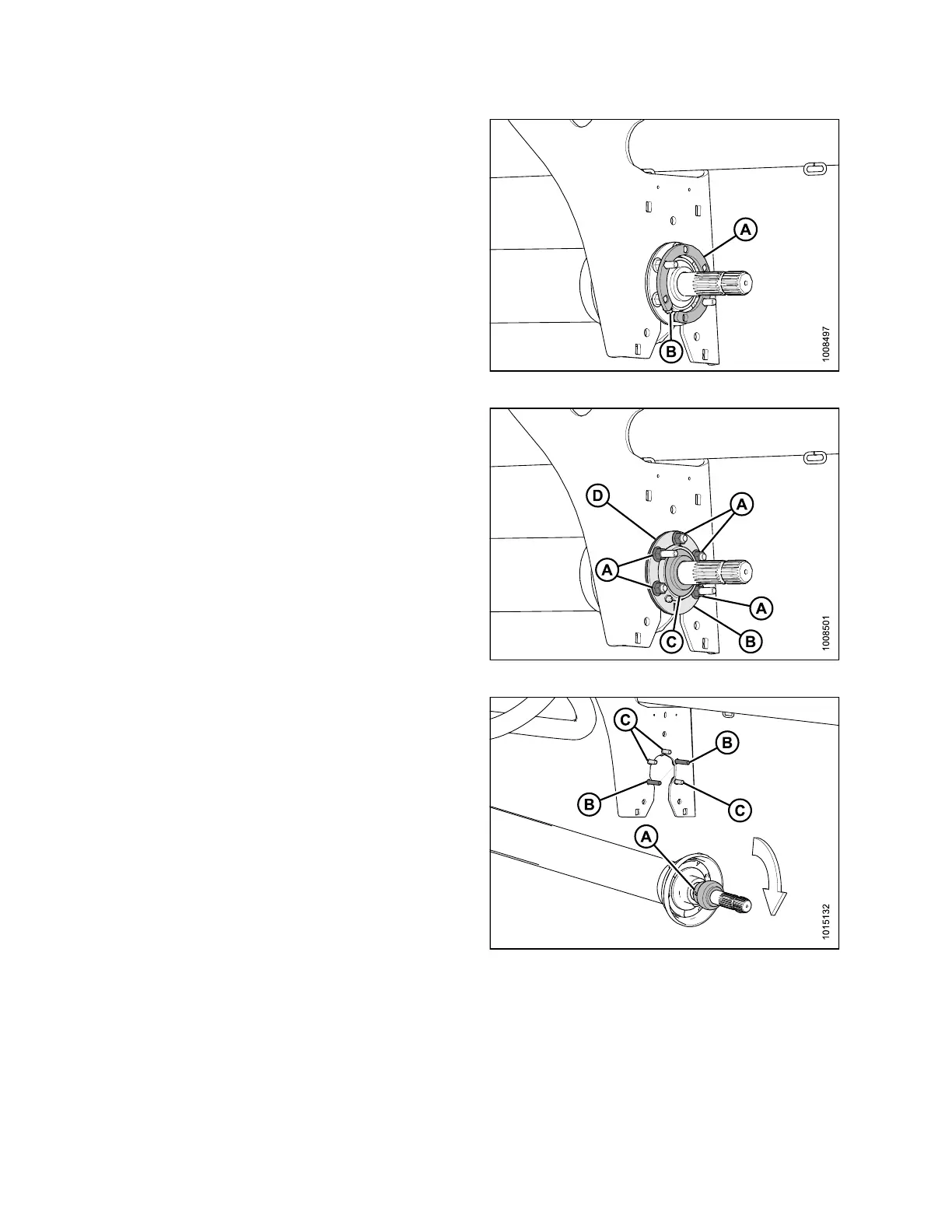
Figure 4.156: Spacer
7. Support driveline and remove five nuts (A), flange with
grease fittin g (B), ball bearing (C), flange (D), and
unlock bearing loc k collar.
Figure 4.157: Ball Bearing and Flanges
8. Unlock the bearing lock collar (A) by rotating it in th e
direction opposite to the rotation of the shaft.
9. Slide the be aring lock collar off the driveline shaft.
10. Lower the driveline from the center support.
NOTE:
Bolts may or may not be remov ed. If removing
bolts, note position of the long (B) an d
short (C) bolts.
Figure 4.158: Bearing Lock Collar
147910 188 Revision A