OPERATION
Table 3.4 Hydraulic System Hoses
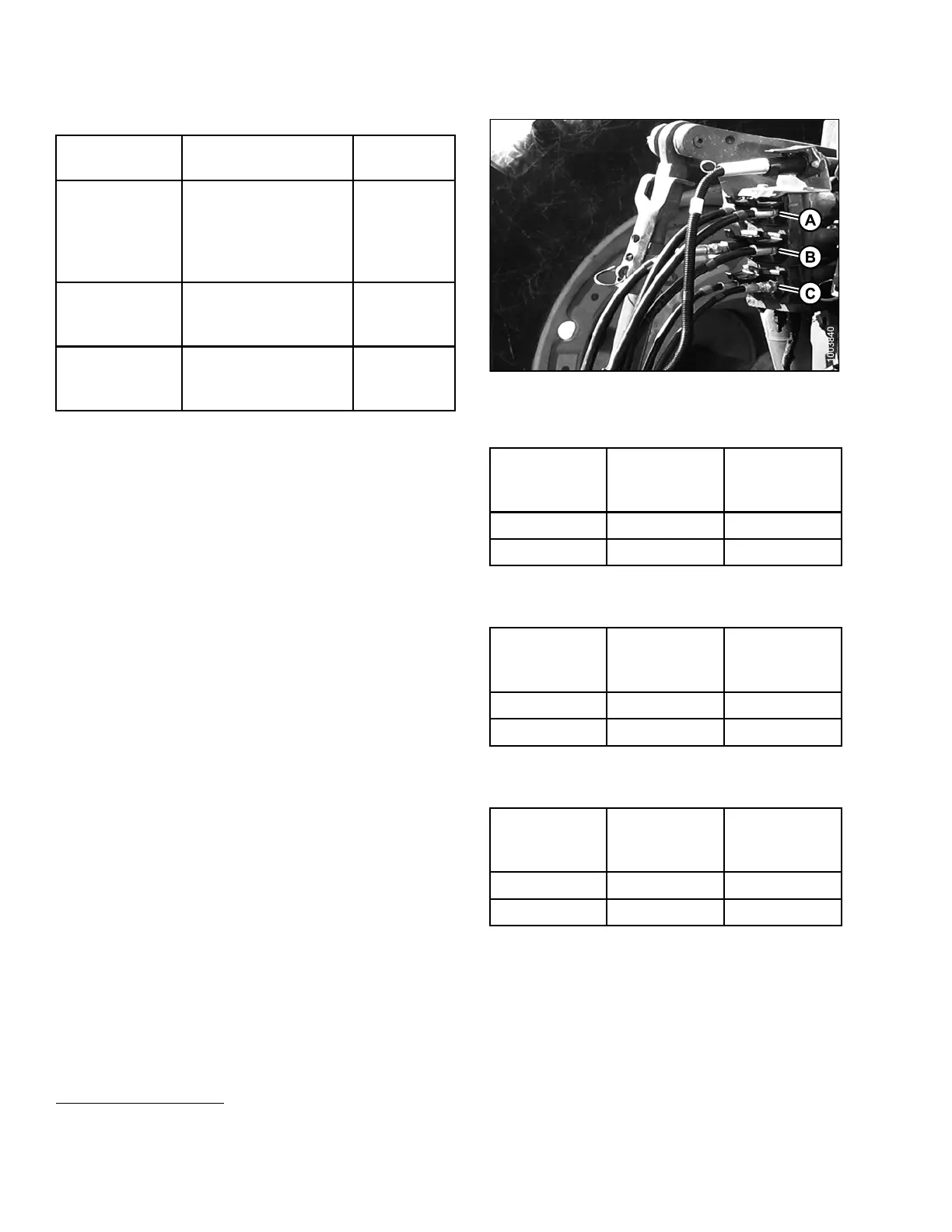
System Hose Identification
Tractor
Hydra ulics
Lift (A)
Red#1-pressure
Blue #1 - return (only
with Road Friendly
Transport
™
system
installed)
Control 1
Swing/
Transport (
B)
Red#2-pres
sure
Blue #2 - ret
urn
Control 2
Tilt (C)
6
Red#3-pressure
Blue #3 - return Control 3
Figure 3.34: Hydraulic Connections
1. Connect the lift c
ylinder hose (red label with #1) to
the tractor’s hy
draulic receptacle. The second hose
(blue #1) is requ
ired only when the Road Friendly
Transport
™
syst
em in stalled. Refer to Table 3. 5 Lift
System, page 48.
Table 3.5 Lift Sy
stem
Control Lever
Position
Cylinder
Movement
Mower
Conditioner
Movement
Forward Retract Lower
Backward Extend Raise
2. Connect the two hitch swing cylinder hoses (labelled
#2) t o the tractor hydraulic receptacles. Refer to Table
3.6 Hitch Swing and Transport System, page 48.
Table 3.6 Hitch Swing and Transport System
Control Lever
Position
Cylinder
Movement
Mower
Conditioner
Direction
Forward Extend Right
Backward Retract
Left
3. Connect the two mower condi
tioner tilt cylinder hoses
(labelled #3) to the tracto
r hyd ra ulic receptacles. Refer
to Table 3.7 Mower Conditi
oner Tilt System, page 4 8 .
(Not required with mechan
ical cen te r-lin k).
Table 3.7 Mower Conditione
rTiltSystem
Control Lever
Position
Cylinder
Movement
Mower
Conditioner
Movement
Forward Retract Lower
Backward Extend Raise
6. Available with h ydraulic tilt option ins talled.
147910 48 Revision A