OPERATION
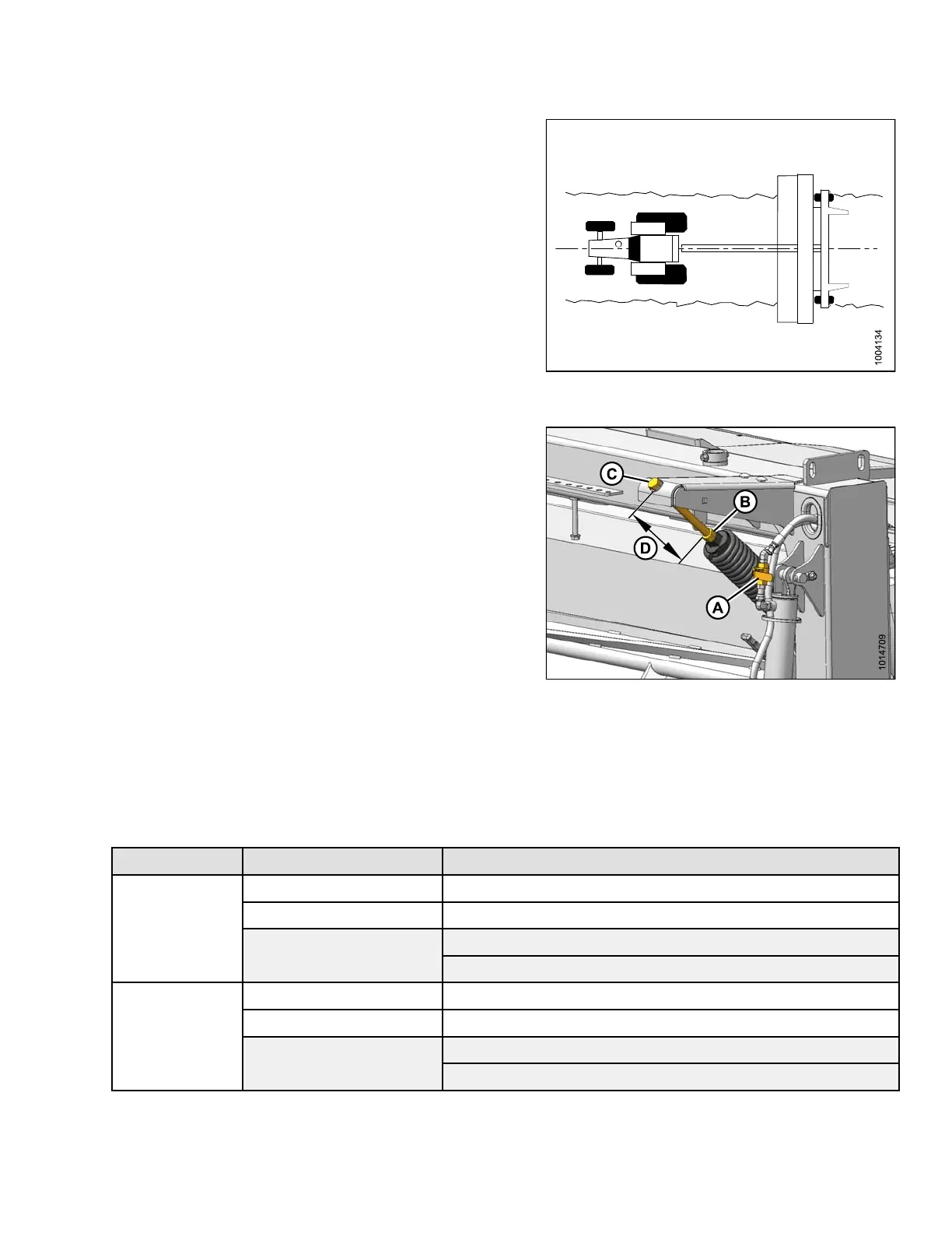
1. Center the mower conditioner directly behind the
tractor.
2. Raise mower conditioner fully, shut off engine, and
remove key.
Figure 3.93: Mower Conditioner Centered
behind Tractor
3. Close the mower conditioner’s lift cylinder lock-out
valve (A) on each lift cylinder by turning the handle to
the horizontal position.
4. Loosen jam nut (B) away from the spring.
5. Turn the adjuster bolt (C) to achieve the recommended
measurement (D) for the conditioner type.
• Turn bolt clockwise (towards spring) to increase float
• Turn bolt counterclockwise (away from spring) to
decrease float
6. Tighten jam nut (B) against spring.
7. Measure the length of exposed thread (D) on the float
spring tension bolts. Refer to Table 3.9 Recommended
Float Settings, page 81.
8. Repeat Steps 4., page 81 to 7., page 81 on the
opposite side of the mower conditioner.
9. Open the cylinder lock-out valve (A) on each lift cylinder
by turning the handle to the vertical position.
Figure 3.94: Lift Cylinder Lock-Out Valve, Jam
Nut, and Adjuster Bolt
Table 3.9 Recommended Float Settings
Header Size Conditioner Type Length of Exposed Thread
No conditio
ner
11–11-5/32 in. (280–290 mm)
Roll conditioner
4-3/4–5-1
/8 in. (120–130 mm)
Right side: 5-3/4–6-1/8 in. (145–155 mm)
13 foot
Finger conditioner
Left side: 4-1/2–4-15/16 in. (115–125 mm)
No conditioner
9–9-1/2
in. (230–240 mm)
Roll conditioner
2-3/4–3-1/8 in. (70–80 mm)
Right side: 3-3/4–4-1/8 in. (95–105 mm)
16 foot
Finger c
onditioner
Left s
ide: 2-1/2–3 in. (65–75 mm)
147910 81 Revision A