F16
INTAKE-AIR SYSTEM
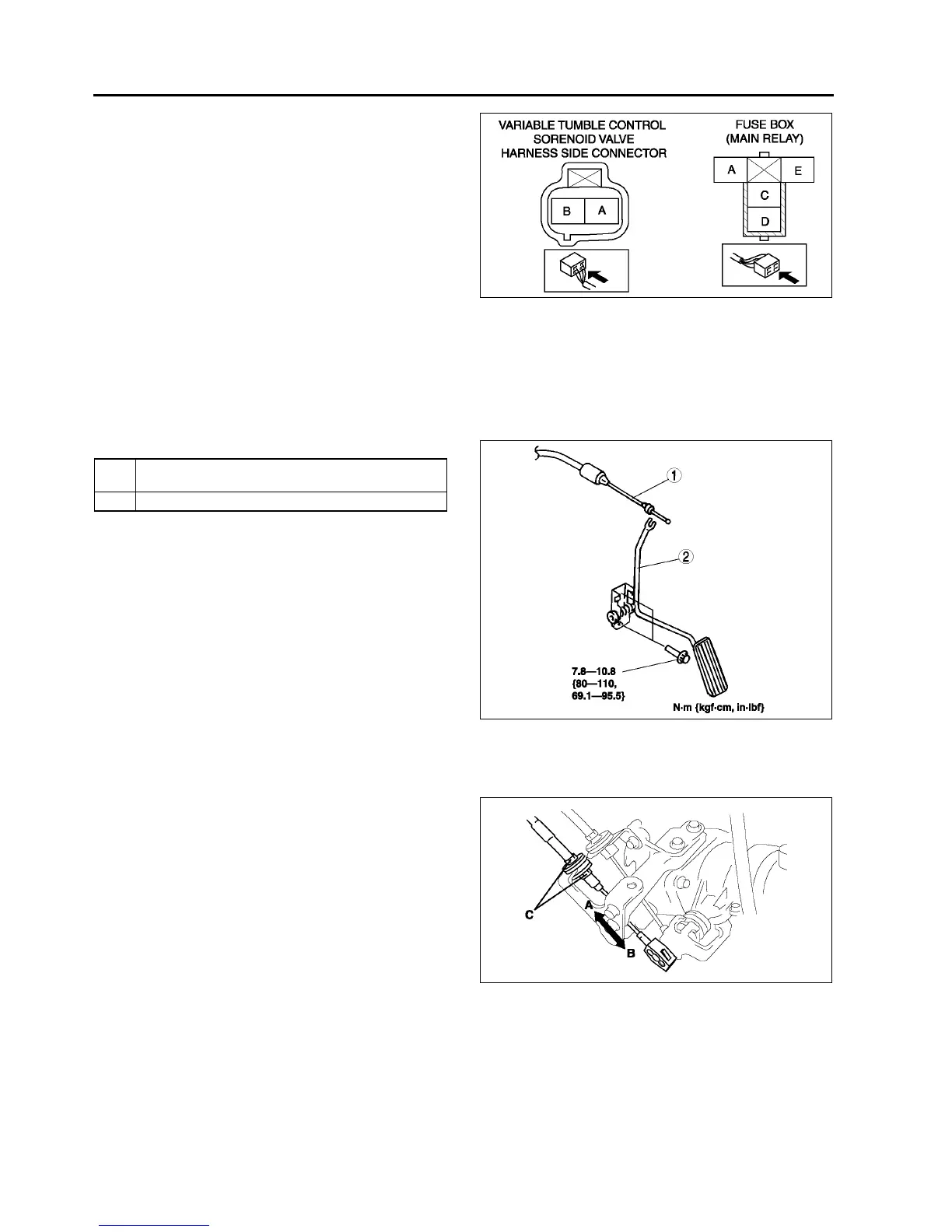
2. Inspect the following wiring harness for open or
short (continuity check).
Open circuit
• If there is no continuity, the circuit is open. Repair
or replace the harness.
Variable tumble control solenoid valve
terminal B (harness-side) and PCM terminal
4T
Variable tumble control solenoid valve
terminal A (harness-side) and main relay
terminal C (harness-side)
Short circuit
• If there is continuity, the circuit is shorted. Repair
or replace the harness.
Variable tumble control solenoid valve terminal B (harness-side) and body GND
Variable tumble control solenoid valve terminal A (harness-side) and power supply
End Of Sie
ACCELERATOR PEDAL REMOVAL/INSTALLATION
A6E391041600W01
1. Remove in the order indicated in the table.
2. Install in the reverse order of removal.
.
Accelerator Cable Installation Note
1. Carry out the ACCELERATOR CABLE
INSTALLATION/ADJUSTMENT procedure after
installing the accelerator cable. (See F16
ACCELERATOR CABLE INSPECTION/
ADJUSTMENT.)
End Of Sie
ACCELERATOR CABLE INSPECTION/ADJUSTMENT
A6E391041660W01
1. Verify that the throttle valve is closed.
2. Pull the accelerator cable in the directions of A
and B, and measure the free play.
• If not as specified, adjust by turning locknut C.
Free play
1.03.0 mm {0.040.11 in}
Tightening torpue
9.814.7 N·m {100150 kgf·cm, 87130
in·lbf}
End Of Sie
A6E3910W017
1 Accelerator cable
F16 Accelerator Cable Installation Note)
2 Accelerator pedal
A6E3910W033
A6E3910W030