N10
ENGINE SPEED SENSING POWER STEERING
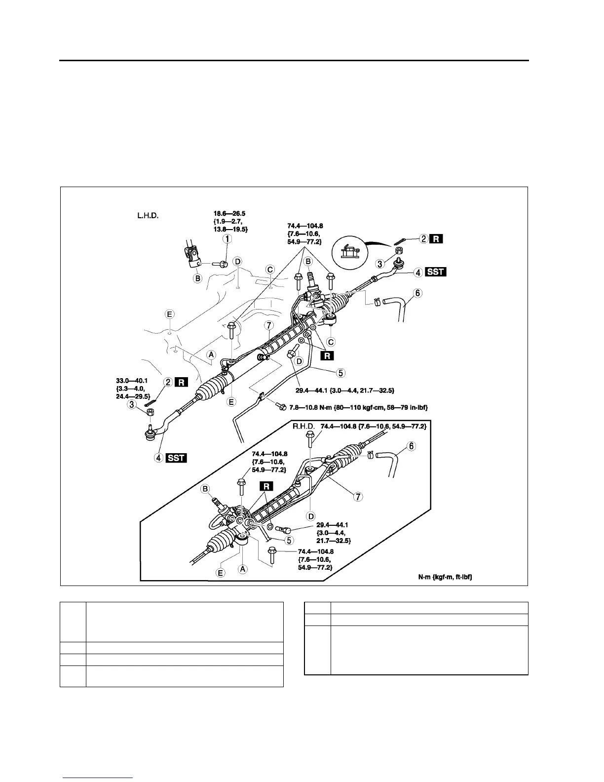
STEERING GEAR AND LINKAGE REMOVAL/INSTALLATION
A6E661432960W01
Caution
•
••
• Performing the following procedures without first removing the ABS wheel-speed sensor may
possibly cause an open circuit in the harness if it is pulled by mistake. Before performing the
following procedures, remove the ABS wheel-speed sensor (axle side) and fix it to an appropriate
place where the sensor will not be pulled by mistake while servicing the vehicle.
1. Remove in the order indicated in the table.
2. Install in the reverse order of removal.
3. After installation, inspect the toe-in. (See R5 FRONT WHEEL ALIGNMENT.)
.
A6E0612W108
1 Bolt (intermediate shaft)
(See N11 Bolt (Intermediate Shaft) Removal Note)
(See N12 Bolt (Intermediate Shaft) Installation
Note)
2 Cotter pin
3 Nuts (tie-rod end ball joint)
4 Tie-rod end ball joint
(See N11 Tie-rod End Ball Joint Removal Note)
5 Pressure pipe
6 Return pipe
7 Steering gear and linkage
(See N11 Steering Gear and Linkage Removal
Note)
(See N12 Steering Gear and Linkage Installation
Note)