K68
ON-BOARD DIAGNOSTIC
DTC P0715
A6E567001030W12
Diagnostic procedure
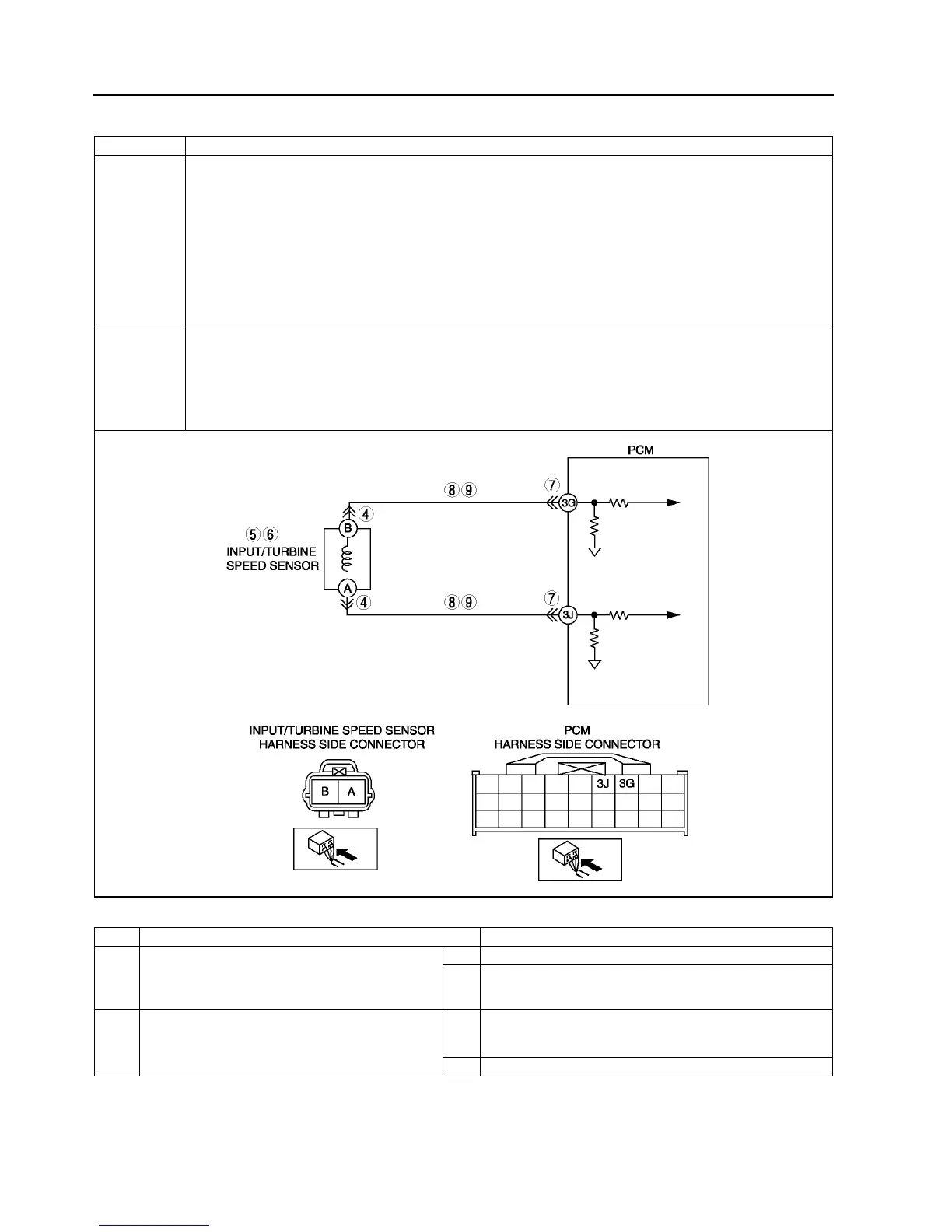
DTC P0715 Input/turbine speed sensor circuit malfunction
DETECTION
CONDITION
• When all conditions below satisfied and 0.7 second or more have passed.
D, S or L range of TR switch input.
Driving vehicle with vehicle speed 40 km/h {25 mph} or above.
Input/turbine speed sensor signal not input.
Diagnostic support note:
• This is a continuous monitor (CCM).
• MIL illuminates if PCM detects the above malfunction conditions during first drive cycle.
• PENDING CODE is not available.
• FREEZE FRAME DATA is available.
• HOLD indicator light flashes.
• DTC is stored in the PCM memory.
POSSIBLE
CAUSE
• Input/turbine speed sensor malfunction
• Short to ground between input/turbine speed sensor terminal A and PCM terminal 3J
• Short to ground between input/turbine speed sensor terminal B and PCM terminal 3G
• Open circuit between input/turbine speed sensor terminal A and PCM terminal 3J
• Open circuit between input/turbine speed sensor terminal B and PCM terminal 3G
• Damaged connectors between input/turbine speed sensor and PCM
• PCM malfunction
STEP INSPECTION ACTION
1 VERIFY FREEZE FRAME DATA HAS BEEN
RECORDED
• Has FREEZE FRAME PID DATA been
recorded?
Yes Go to next step.
No Record FREEZE FRAME PID DATA on repair order, then
go to next step.
2 VERIFY RELATED REPAIR INFORMATION
AVAILABILITY
• Check for related Service Bulletins availability.
• Is any related repair information available?
Yes Perform repair or diagnosis according to available repair
information.
• If vehicle is not repaired, go to next step.
No Go to next step.