ON-BOARD DIAGNOSTIC
F85
F
DTC P0103
A6E397001084W10
Diagnostic procedure
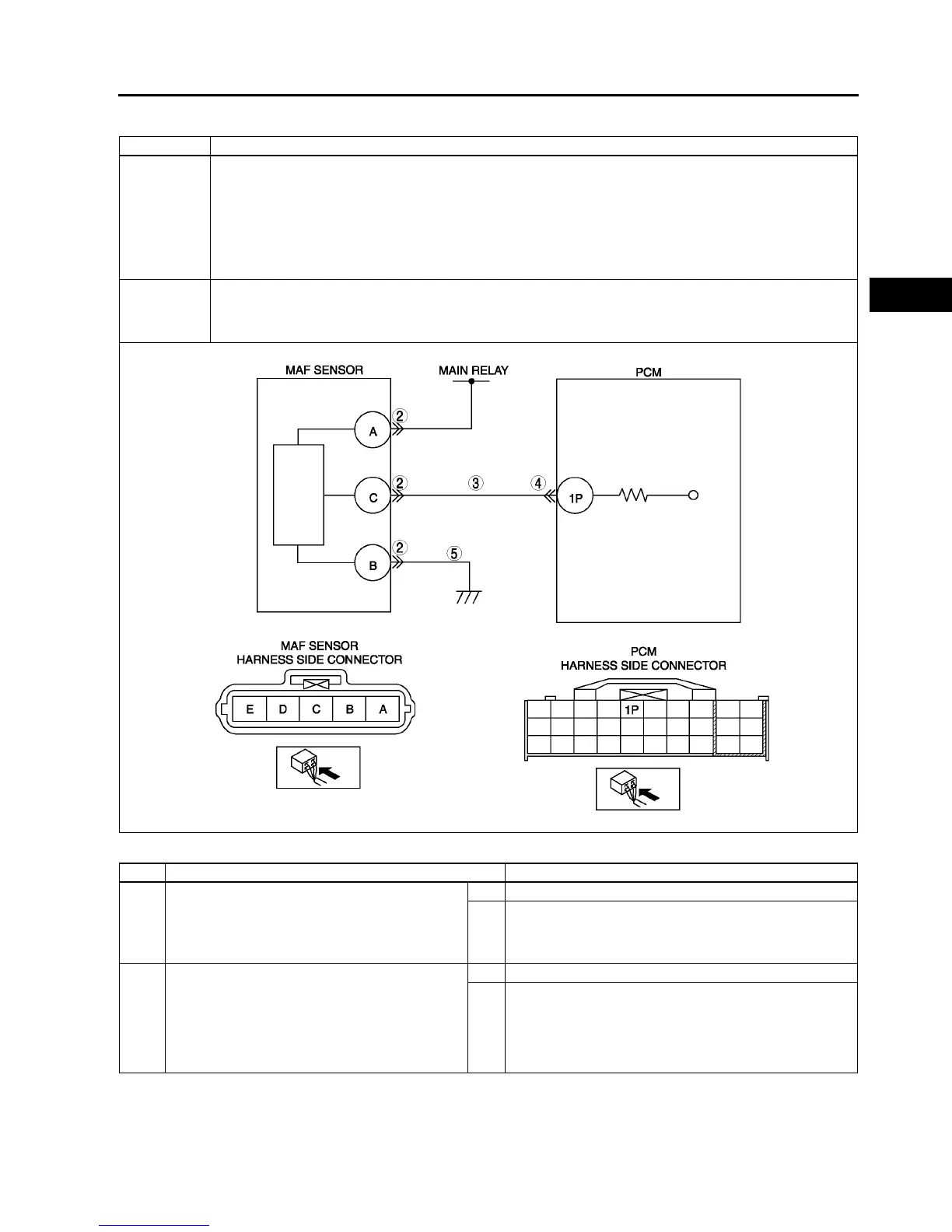
DTC P0103 MAF circuit high input
DETECTION
CONDITION
• PCM monitors input voltage from MAF sensor when engine running. If input voltage at PCM terminal 1P is
above 4.9 V, PCM determines that MAF circuit has malfunction.
Diagnostic support note
• This is a continuous monitor (CCM).
• MIL illuminates if PCM detects the above malfunction condition during first drive cycle.
• PENDING CODE is available if PCM detects the above malfunction condition.
• FREEZE FRAME DATA is available.
• DTC is stored in the PCM memory.
POSSIBLE
CAUSE
• MAF sensor malfunction
• Connector or terminal malfunction
• Short to power in wiring between MAF/IAT sensor terminal C and PCM terminal 1P.
• Open circuit in MAF/IAT sensor ground circuit
STEP INSPECTION ACTION
1 PERFORM DTC CONFIRMATION PROCEDURE
• Perform DTC CONFIRMATION PROCEDURE.
(See F66 DTC CONFIRMATION
PROCEDURE.)
• Is same DTC present?
Yes Go to next step.
No Intermittent concern exists. Go to INTERMITTENT
CONCERN TROUBLESHOOTING procedure.
(See F227 INTERMITTENT CONCERN
TROUBLESHOOTING.)
2 INSPECT POOR CONNECTION OF MAF
SENSOR CONNECTOR
• Turn ignition key to OFF.
• Disconnect the MAF/IAT sensor connector.
• Inspect for poor connection (damaged, pulled-
out terminals, corrosion, etc.).
• Is there any malfunction?
Yes Repair or replace terminals, then go to Step 6.
No Go to next step.