TROUBLESHOOTING (ABS/TCS/DYNAMIC STABILITY CONTROL)
P119
P
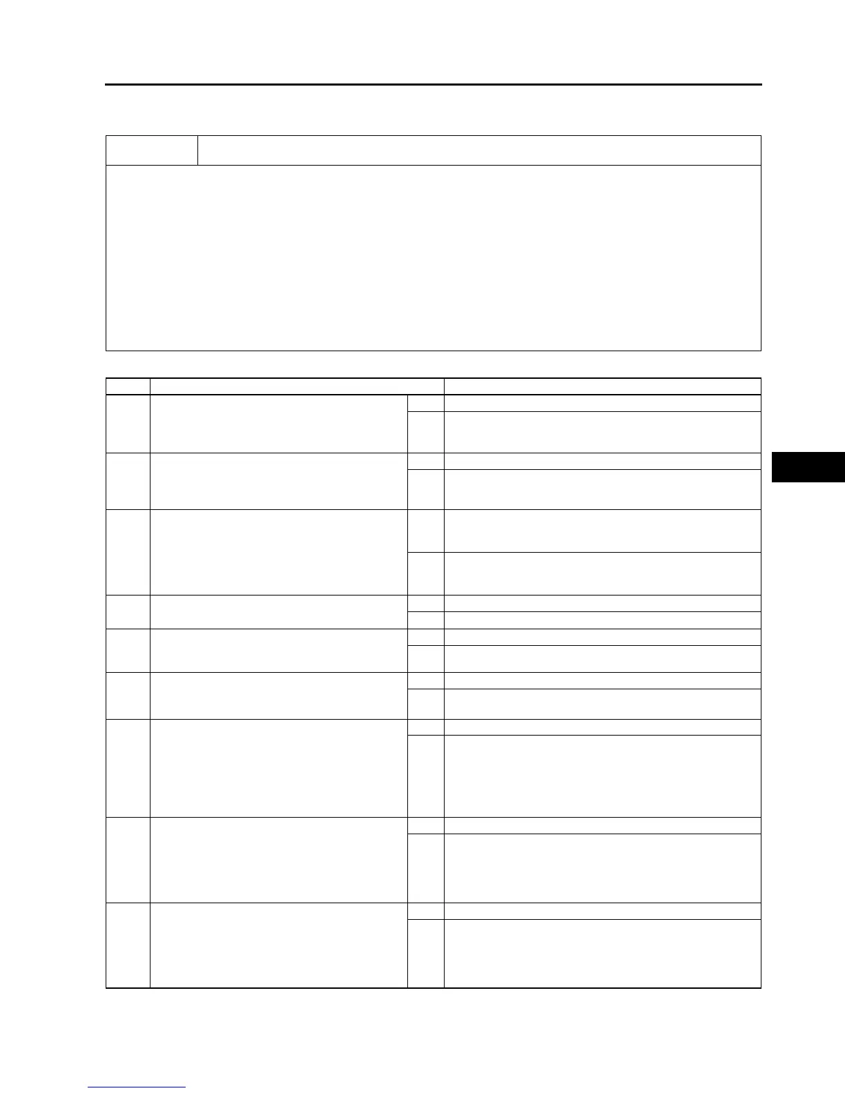
NO.2 ANY OF THE FOLLOWING LIGHTS STAY ON: (ABS WARNING LIGHT, BRAKE SYSTEM WARNING
LIGHT, DSC INDICATOR LIGHT AND/OR
DSC
OFF LIGHT)
A6E699067650W17
Diagnostic procedure
End Of Si e
2
Any of the following lights stay on: (ABS warning light, BRAKE system warning light, DSC indicator
light and/or DSC OFF light)
[TROUBLESHOOTING HINTS]
• Brake fluid amount is low.
• Parking brake does not release.
• No connection at DSC HU/CM connector
(when DSC HU/CM connector comes off, ABS warning light and BRAKE system warning light illuminate.)
• DSC HU/CM detected malfunction (input and output device malfunction)
• DSC HU/CM detects low voltage in power supply.
• DSC HU/CM ground malfunction
(when DSC HU/CM ground is not securely connected, ABS warning light and BRAKE system warning light
illuminate but diagnostic trouble code does not display)
• DSC HU/CM does not operate (DSC HU/CM malfunction.)
• DSC OFF light circuit shorted in ground (when DSC OFF circuit is shorted in ground, DSC OFF light illuminated.)
• ABS warning light circuit or BRAKE system warning light circuit open
(when the harness is open between DSC HU/CM and each warning light, each warning light illuminates)
STEP INSPECTION ACTION
1 INSPECT BRAKE FLUID AMOUNT AND
VERIFY THAT PARKING BRAKE RELEASES
• Is brake fluid amount normal?
• Is parking brake lever released?
Yes Go to next step.
No Add brake fluid or release parking brake lever.
2 CHECK FOR DTCS IN DSC HU/CM
• Check the DTC for the DSC ON-BOARD
DIAGNOSTIC SYSTEM.
• Have DTCs been recorded in memory?
Yes Perform inspection using appropriate DTC.
No Go to next step.
3 CHECK TO SEE WHETHER MALFUNCTION
IS IN CONTROL MODULE CONNECTOR,
TERMINAL OR OTHER
• Do ABS warning light and BRAKE system
warning light go off after 4 seconds with
ignition switch on?
Yes Temporary poor connection in control module connector.
Inspect DSC HU/CM connector, then go to Step 6.
Inspect DSC HU/CM connector terminal, then go to Step 7.
No Go to next step.
4 INSPECT BATTERY
• Is battery voltage normal?
Yes Go to next step.
No Inspect battery and charging system.
5 INSPECT CHARGING SYSTEM
• Is battery voltage normal with electrical load
(A/C, headlight, etc.) on and engine idling?
Yes Go to next step.
No Inspect charging system (drive belt tension, generator, etc.).
6 VERIFY THAT DSC HU/CM CONNECTOR IS
CONNECTED
• Is DSC HU/CM securely connected?
Yes Go to next step.
No Connect DSC HU/CM connector securely, then go to next
step.
7 VERIFY THAT DSC HU/CM CONNECTOR
TERMINAL OR RELATED CONNECTOR
TERMINALS ARE CONNECTED
• Are DSC HU/CM connector terminal or
instrument cluster connector terminal etc.
related connector terminals securely
connected?
Yes Go to next step.
No Connect DSC HU/CM connector terminal etc. related
connector terminals securely.
8 INSPECT WIRING HARNESS BETWEEN
INSTRUMENT CLUSTER AND DSC HU/CM
FOR CONTINUITY
• Is there continuity between each warning
light terminal of instrument cluster and DSC
HU/CM connector terminal?
Yes Go to next step.
No Repair malfunctioning part.
9 INSPECT WIRING HARNESS BETWEEN
INSTRUMENT CLUSTER AND DSC HU/CM
FOR SHORT IN GROUND
• Is there continuity between each indicator
light terminal of DSC HU/CM and ground?
Yes Repair malfunctioning part.
No Inspect power supply harness and ground harness of DSC
HU/CM.
If above wiring harness are okay, replace DSC HU/CM.
If above wiring harness are malfunctioning, repair
malfunctioning wiring harness.