K14
AUTOMATIC TRANSAXLE
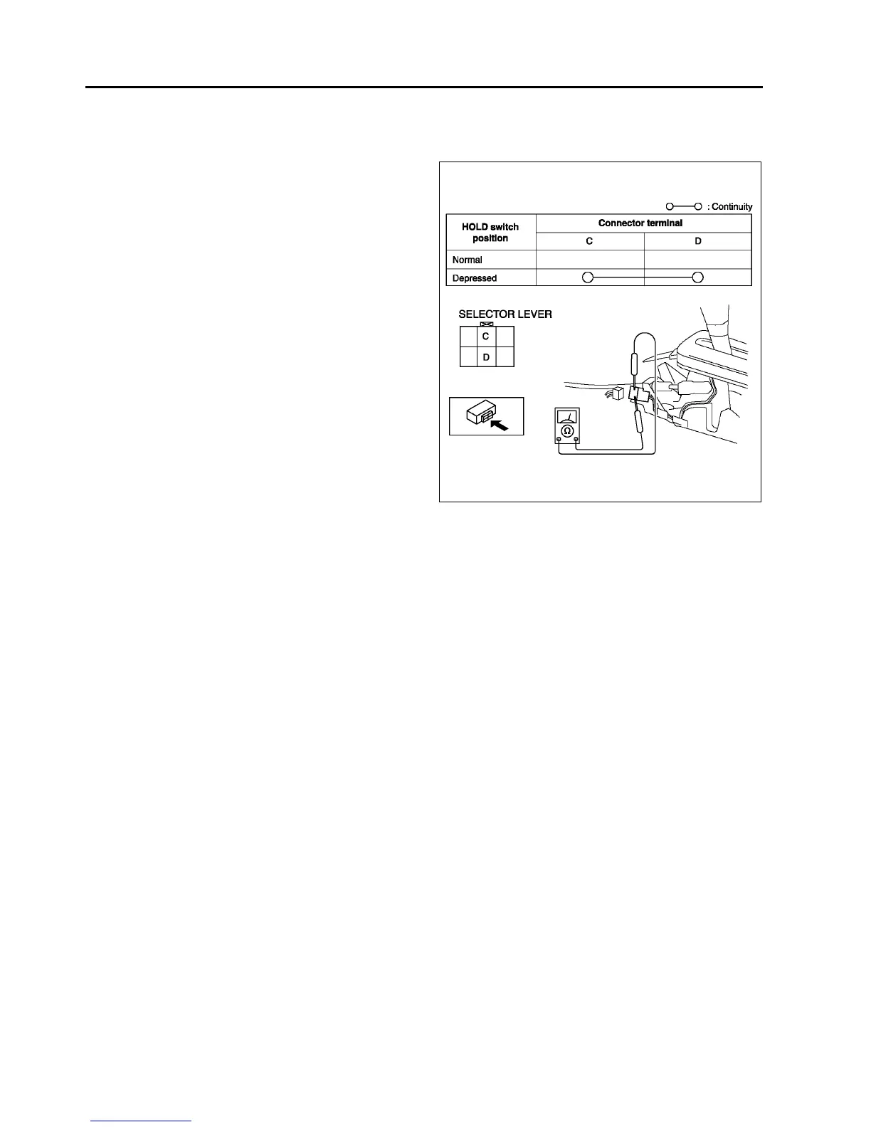
Continuity Inspection of
1. Disconnect the negative battery cable.
2. Remove the console.
3. Disconnect the HOLD switch connector.
4. Inspect continuity at the HOLD switch.
• If the switch is okay, inspect the wiring
harness. (HOLD switchPCM, HOLD
switchBody ground)
• If not as specified, replace the HOLD switch.
(See K14 HOLD SWITCH REMOVAL/
INSTALLATION.)
5. Connect the HOLD switch connector.
6. Install the console.
7. Connect the negative battery cable.
End Of Sie
HOLD SWITCH REMOVAL/INSTALLATION
A6E561446030W02
1. Disconnect the negative battery cable.
2. Remove the console.
3. Disconnect the connector and remove the HOLD switch terminals. (See K51 SELECTOR LEVER
DISASSEMBLY/ASSEMBLY.)
4. Remove the selector lever knob component.
5. Remove the HOLD switch.
6. Install the HOLD switch to selector lever knob component.
7. Install selector lever knob component.
Tightening torque
15.6822.54 N·m {1.5992.298 kgf·m, 1216 ft·lbf}
8. Install the HOLD switch terminals and connect the connector.
9. Install the console.
10. Connect the negative battery cable.
End Of Sie
TRANSAXLE RANGE (TR) SWITCH INSPECTION
A6E561419440W01
Operating Inspection
1. Verify that the starter operates only when the ignition switch is at the START position with the selector lever in
P or N position.
• If not as specified, adjust the TR switch.
2. Verify that the back-up lights illuminate when shifted to R position with the ignition switch at the ON position.
• If not as specified, adjust the TR switch.
Continuity Inspection
Caution
•
••
• Water or foreign objects entering the connector can cause a poor connection or corrosion. Be
sure not to drop water or foreign objects on the connector when disconnecting it.
1. Disconnect the negative battery cable.
2. Remove the air cleaner component. (See F10 INTAKE-AIR SYSTEM REMOVAL/INSTALLATION.)
A6E5614W007