K24
AUTOMATIC TRANSAXLE
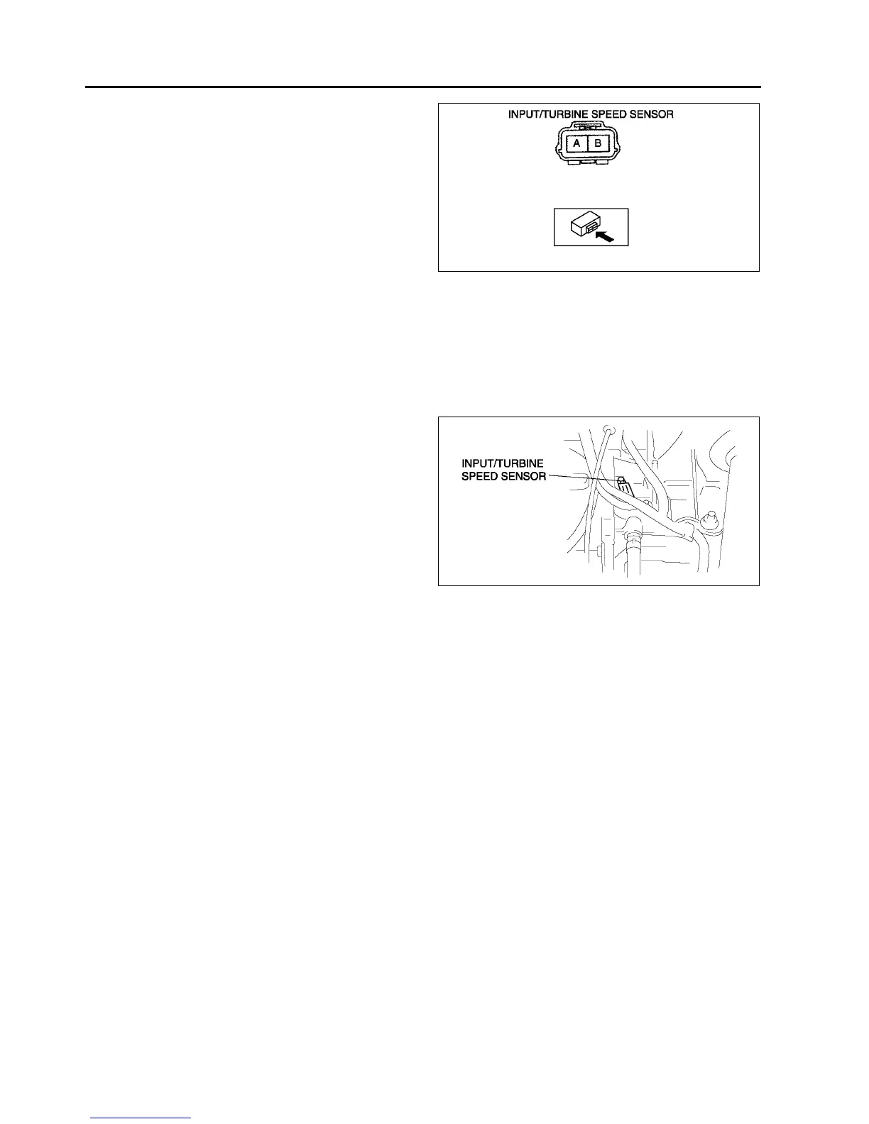
5. Measure resistance between the terminals of the
input/turbine speed sensor.
• If not as specified, replace the input/turbine
speed sensor.
Resistance
250600 ohms (ATF temperature: 40160
°
°°
°C {40320 °
°°
°F})
6. Connect the input/turbine speed sensor
connector.
7. Install the air cleaner component. (See F10
INTAKE-AIR SYSTEM REMOVAL/
INSTALLATION.)
8. Install the battery and battery tray.
9. Connect the negative battery cable.
End Of Sie
INPUT/TURBINE SPEED SENSOR REMOVAL/INSTALLATION
A6E561421550W04
1. Disconnect the negative battery cable.
2. Remove the battery and battery tray.
3. Remove the air cleaner component. (See F10 INTAKE-AIR SYSTEM REMOVAL/INSTALLATION.)
4. Disconnect the input/turbine speed sensor
connector.
5. Remove the input/turbine speed sensor.
6. Apply ATF to a new O-ring and install it on a new
input/turbine speed sensor.
7. Install the input/turbine speed sensor.
Tightening torque
811 N·m {82112 kgf·cm, 7197 in·lbf}
8. Connect the input/turbine speed sensor
connector.
9. Install the air cleaner component. (See F10
INTAKE-AIR SYSTEM REMOVAL/
INSTALLATION.)
10. Install the battery and battery tray.
11. Connect the negative battery cable.
End Of Sie
VEHICLE SPEEDOMETER SENSOR (VSS) INSPECTION
A6E561401030W05
Visual Inspection
1. Remove the VSS. (See K26 VEHICLE SPEEDOMETER SENSOR (VSS) REMOVAL/INSTALLATION.)
2. Make sure that the sensor is free of any metallic shavings or particles.
• If any are found on the sensor, clean them off.
3. Install the VSS. (See K26 VEHICLE SPEEDOMETER SENSOR (VSS) REMOVAL/INSTALLATION.)
Wave profile Inspection
1. Remove the PCM. (See F43 PCM REMOVAL/INSTALLATION.)
2. Connect WDS or equivalent to DLC connector.
3. Connect osilloscope test leads to the following PCM connector terminals.
• (+) lead: PCM terminal 3C
• (-) lead: PCM terminal 1D
4. Start the engine.
5. Monitor VSS PID.
A6E5614W031
A6E5614W030