AUTOMATIC TRANSAXLE
K25
K
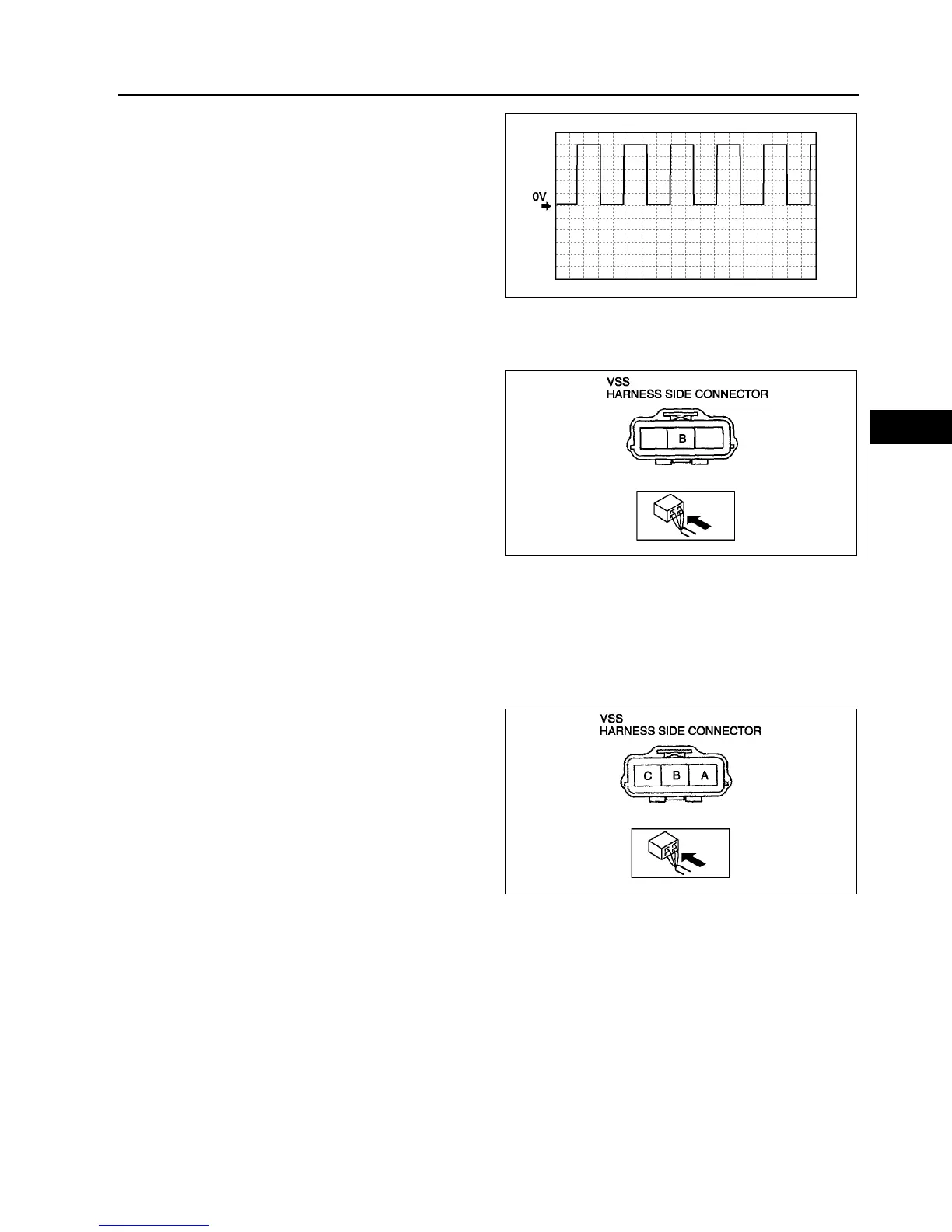
6. Inspect wave profile.
• PCM terminal: 3C (+) - 1D (-)
• Oscilloscope setting: 1 V/DIV (Y), 2.5 ms/DIV
(X), DC range
• Vehicle condition: drive the vehicle with 32
km/h{20 mph}
If wave profile or voltage are out of
specifications, carry out the Open Circuit
Inspection or Short Circuit Inspection
Power Supply Voltage Inspection
1. Disconnect the VSS connector.
2. Turn the ignition switch to ON.
3. Measure voltage at VSS connector terminal B
(wiring harness side).
Specification
4.55.5 V
• If voltage is okay, go to Open Circuit
Inspection and Short Circuit Inspection.
• If voltage is wrong, repair wiring harness
between VSS and PCM.
Open Circuit Inspection
1. Inspect the following circuit for open.
• Power circuit (VSS connector terminal A to main relay terminal D)
• Ground circuit (VSS connector terminal C to GND)
• If an open circuit or short circuit is found, repair the malfunctioning wiring harness.
• If there are no open or short circuits, perform the sensor rotor inspection.
Short Circuit Inspection
1. Inspect the following circuit for short.
• Power circuit (VSS connector terminal A to
main relay terminal D)
• If an open circuit or short circuit is found,
repair the malfunctioning wiring harness.
• If there are no open or short circuits, perform
the sensor rotor inspection.
Sensor Rotor Inspection
1. Remove the VSS. (See K26 VEHICLE SPEEDOMETER SENSOR (VSS) REMOVAL/INSTALLATION.)
2. Shift the selector lever to N position.
3. Inspect sensor rotor surface via VSS installation hole while rotating the front tire manually.
(1) Is sensor rotor free of damage and cracks?
(2) Is sensor rotor free of any metallic shavings or particles?
• If sensor rotor is okay, replace the VSS.
• If there is a problem, clean or replace the sensor rotor.
End Of Sie
A6E5614W102
A6E5614W033
A6E5614W035