EMISSION SYSTEM
F41
F
PCV VALVE INSPECTION
A6E391613890W01
1. Disconnect the negative battery cable.
2. Remove the intake maniforld.(see F10 INTAKE-AIR SYSTEM REMOVAL/INSTALLATION.)
3. Remove the PCV valve.
4. Blow through the valve and verify that air flows as
specified.
• If not as specified, replace the PCV valve.
Specification
End Of Sie
THREE-WAY CATALYTIC CONVERTER (TWC) INSPECTION
A6E391620500W01
Note
• Make sure that no HO2S DTCs have been detected. If detected, this inspection is not applicable for TWC
inspection.
1. Connect the WDS or equivalent and monitor PIDs as following.
• Monitor the right TWC using O2S11 PID for upstream HO2S and O2S12 PID for downstream HO2S.
2. Begin to monitor the appropriate PIDs.
3. Drive the vehicle for 10 min at 6596 km/h {4060 mph} to allow the front catalytic converter to reach
operating temperature.
4. Stop the vehicle and leave it in a safe place.
5. Let the engine idle.
6. Record PIDs for 1 min.
7. Select the appropriate PIDs and read the graph.
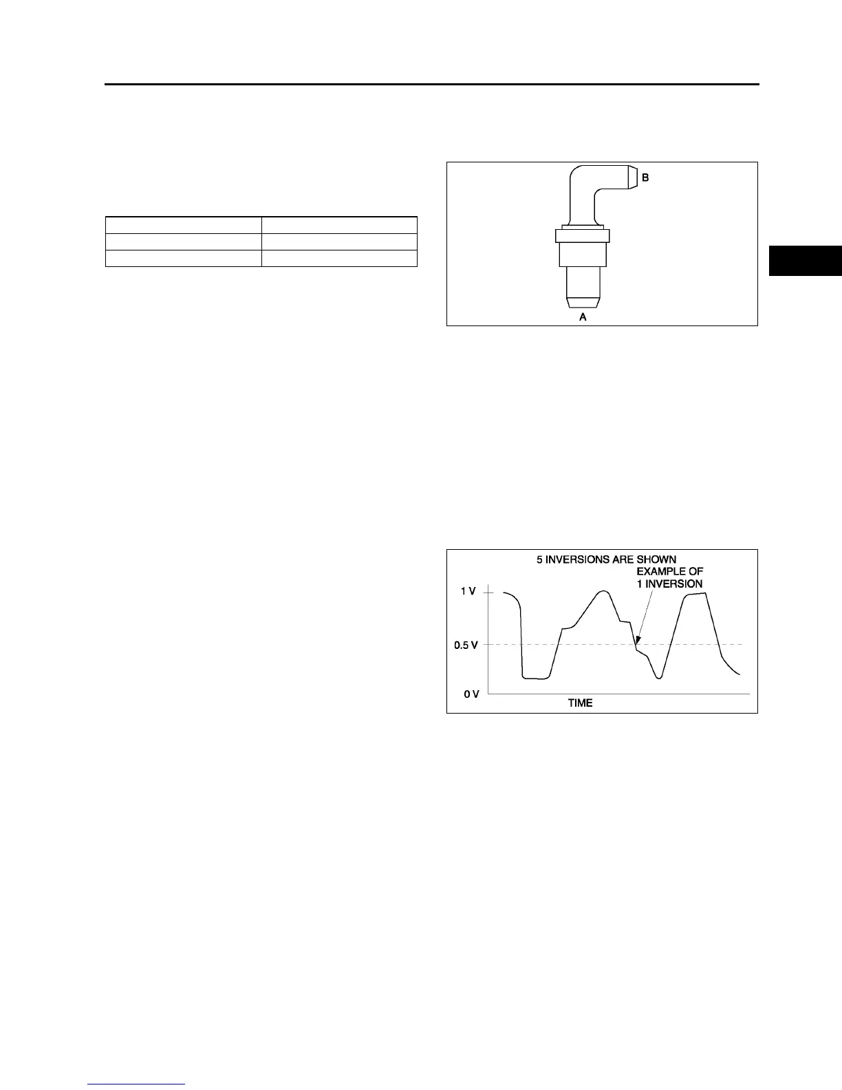
8. Count the number of times (inversions) that the
upstream HO2S graph line actually crosses the
0.5 V line.
9. Count the number of times (inversions) that the
downstream HO2S graph line actually crosses
the 0.5 V line.
Note
• Do not count the number of peaks. Refer to
the graph.
10. Using the following equation, calculate the value
of ratio.
Equation
RATIO = Upstream HO2S inversion ÷
÷÷
÷ downstream HO2S inversion
• If the ratio is 5.5 or more or there is no downstream HO2S inversion, the TWC is functioning properly.
• If the ratio is less than 1.125, the TWC is not functioning properly. Replace the TWC.
Condition Airflow
Air applied from port A to B Yes
Air applied from port B to A No
A6E3916W007
A6E3916W013